What is the relationship between reference points and connectors? | ||
| ||
-
Vertex or node of a part instance
-
Reference point of a part instance or of an assembly
-
Ground
Using a reference point is often more convenient than using a point or node on the assembly because the same reference point can be used by a rigid body or coupling constraint. In the Part module you can use the Reference Point toolset to create one reference point on each part; additional reference points can be created in the Assembly module, Interaction module, and Load module.
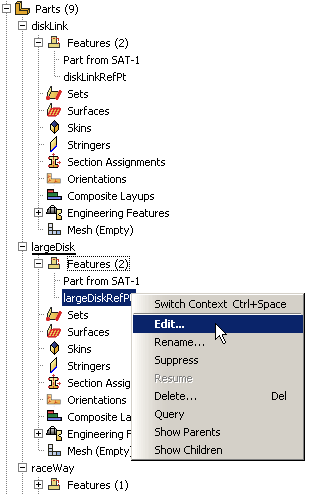
You can use the Model Tree to rename reference points with more descriptive feature names. Descriptive names allow you to more easily associate reference points and wires in a complex model, as shown in Figure 1.

If you want to use different feature names and labels for a reference point on multiple instances of the same part, you must create the reference points in an assembly-related module. You can create a node on a mesh using the Edit Mesh toolset and then select the node to define an endpoint of an assembly-level wire; however, the node is not listed in the Model Tree and has no label in the viewport. For more information on creating and renaming reference points, see The Reference Point toolset. For more information on creating a node on a mesh, see Manipulating nodes.
Each reference point or node that defines an endpoint of an assembly-level wire needs to be associated with the model geometry, even if they are created in the Part module. In many cases you will create a rigid body constraint or a coupling constraint (to distribute forces to an area instead of to a single point) between the reference point or node and a part instance. As a result, the motion of the wire endpoint will be constrained to the motion of the part instance. You create constraints in the Interaction module. For more information, see Understanding constraints.