Stampable, Turnable, and Drillable Surfaces | ||||||
|
| |||||
| CLIENT / Applicable for | SHAPE_CONTROLLER | SHAPE_SENSITIVITY |
|---|---|---|
| SURF_STAMP | OK | OK |
| SURF_TURN | OK | OK |
| SURF_DRILL | OK | - |
Stampable Surface (SURF_STAMP) for Shape Controller
Maintaining a stampable surface during optimization involves defining
a stamping direction. The stamping domain is defined using a node group.
The direction defined by the CLIENT_DIR parameter specifies
the stamping direction. The link condition is defined using the following
parameters:
CLIENT     = SURF_STAMP
CLIENT_DIR = <x_1>,<x_2>,<x_3>
CS         = name_of_coord_system
The main nodes are found using the standard main criterion. The stamping surface is defined using the given stamping direction and the cutting edge automatically generated by Tosca Structure. All nodes of the node group are linked to this surface.
An additional demolding direction can be included:
DEMOLD_DIR = <x_1>,<x_2>,<x_3>
The demolding direction must be orthogonal to the client direction. Therefore, Tosca Structure projects the demold vector onto a plane normal to the client direction.
Important:
|
Stampable Surface (SURF_STAMP) for Shape Sensitivity
A surface is stampable if all nodes lie in the same plane.
Enforcing stampable surfaces is supported for sensitivity-based shape optimizations as well.
The most important parameter is the stamping direction, defined by the CLIENT_DIR parameter.
Another mandatory parameter is the main group, that defines the reference edge or cutting edge for the plane where all nodes shall be moved in.
The link condition is defined using the following
parameters:
CLIENT     = SURF_STAMP
CLIENT_DIR = <x_1>,<x_2>,<x_3>
CS         = name_of_coord_system
MAIN       = NDGR, main_node_group
In the figure below, the green dotted points are used as the stamping area and the green
highlighted edge is used as the main group. 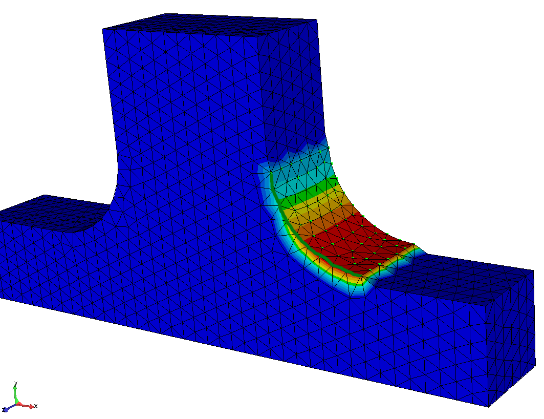
| Important:
|
Turnable Surface (SURF_TURN) for Shape Controller
Maintaining a turnable surface during optimization involves defining a rotation axis. The domain that assures a turnable surface is defined using a node group; all nodes of the specified surface node group are checked for rotation symmetry in the given rotation axis. The link condition is defined using the following parameters:
CLIENT     = SURF_TURN
CLIENT_DIR = <x_1>,<x_2>,<x_3>
CS         = name_of_coord_system
The direction defined by the CLIENT_DIR and the origin
of the coordinate system specify the exact position and direction of
the rotation axis.
The main nodes are found using the standard main criteria. In
addition, the criteria MAIN = AUTO is available for compatibility
reasons with sensitivity-based shape optimization. It can be seen as an alias for
MAIN = MAX. The turning surface is defined using the given
rotation axis and the cutting edge automatically generated by Tosca Structure. All nodes of the node group are linked to this surface.
Important:
|
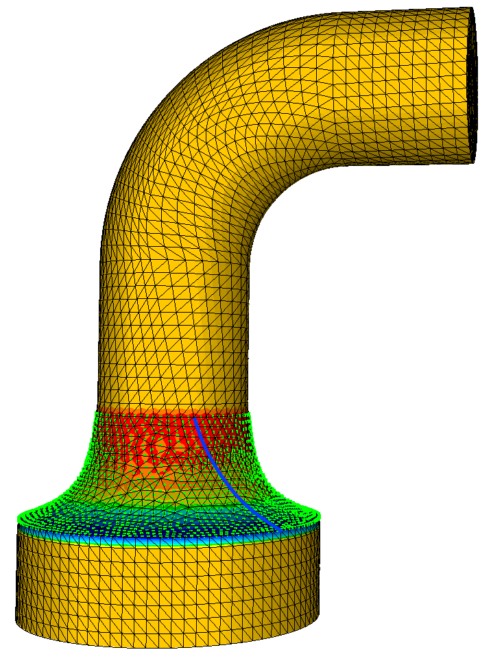
Turnable Surface (SURF_TURN) for Shape Sensitivity
The SURF_TURN manufacturing constraint for sensitivity-based shape optimization can be used
to achieve a turnable or rotational symmetric surface.
The important parameters are the rotational axis CLIENT_DIR, together with the origin,
specified by a coordinate system CS.
Next, the specification of "driving" area (MAIN) is a necessary part of the setup. It can
either be defined by providing a node group (NDGR, <node group name>), which gives very good control,
or by letting Tosca find an appropriate area, which is very simple on the setup side but can fail for complicated surfaces.
The link condition is defined using the following parameters:
CLIENT     = SURF_STAMP
CLIENT_DIR = <x_1>,<x_2>,<x_3>
CS         = name_of_coord_system
MAIN       = NDGR, main_node_group | AUTO
In the figure below, the green dotted points are used as turning area and the blue
highlighted edge is used as the driving area.
| Important:
|
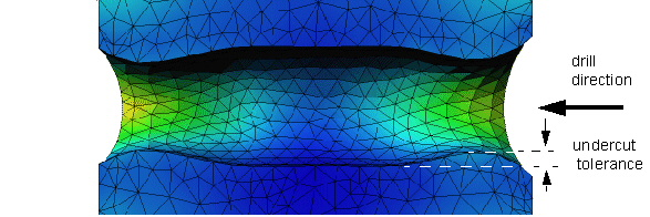
Drillable Surface (SURF_DRILL)
The drill restriction is a combination of the turning and the demolding restriction. Maintaining a drillable surface during optimization involves defining the drill axis and the drill feed. The drilling domain is defined using a node group; all nodes of the specified surface node group are checked for drilling in the given drill direction. The link condition is defined using the following parameter:
CLIENT     = SURF_DRILL
CLIENT_DIR = <x_1>,<x_2>,<x_3>
CS         = name_of_coord_system
ANGLE      = <real> (0° < angle < 45°)
The direction defined by the CLIENT_DIR and the origin
of the coordinate system specify the exact position and direction of
the drill axis, the angle specifies a minimum surface angle.
The shape of the drilling surface can be specified with an additional undercut tolerance. The term 'drilling surface' in this case should be interpreted in a more general sense.
UNDERCUT_TOL = <real> (>0)
 |
Important:
|