Plane Symmetry for Nonsymmetric Meshes (SURF_PLANE_SYM) | ||||||
|
| |||||
| CLIENT / Applicable for | SHAPE_CONTROLLER | SHAPE_SENSITIVITY |
|---|---|---|
| SURF_PLANE_SYM | OK | OK |
To couple nodal displacements symmetrically with respect to a plane, the symmetry plane must be defined in terms of position and orientation. This is supported for symmetric and unsymmetric meshes. The following four parameters are necessary for the definition of the link condition:
CLIENT     = SURF_PLANE_SYM
CLIENT_DIR = <X_1>, <X_2>, <X_3>
CS         = name_of_coord_system
TOL        = tolerance_value
The origin of the coordinate system referenced by CS defines a point on the
symmetry plane. The direction specified by the CLIENT_DIR parameter
defines the normal of the plane. The tolerance value specified by TOL
is used as absolute tolerance in intersection tests and can be used to influence the
behavior on the border of the selected node group.
The symmetry of the nodes (assigned by ND_GROUP in the
DVCON_SHAPE command) is checked against the symmetry plane. For
each node, a reference displacement is calculated for its symmetric "counterpart". This
counterpart is obtained by reflecting the node at the symmetry plane, that is, by
intersecting a line through the node in the plane normal direction with the surface defined
by all selected nodes. The reference displacement is obtained by interpolation of the
optimization displacements of the adjacent nodes. The tolerance is required to find
reference displacements at the border of the selected node group, where it will happen
that nodes do not have an opposite face (with respect to the plane definition) and thus
no intersection points in plane normal directions can be found.
Optional, a strategy to determine node position influence on the result can be chosen:
MAIN = MAX | MIN
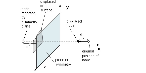
The symmetry is built up by using the maximum (default) or the minimum of the displacement of the selected node (d1 in the following figure) and the interpolated displacement of its plane symmetric counter part (reference displacement d2 in the following figure).
 |
Important:
|
Special Considerations when using Shape Sensitivity
This coupling condition is applicable for sensitivity-based shape optimization. However, the two approaches work in different ways. For the sensitivity-based optimization, the optimization problem is solved only on one halve of the symmetry group and the results (the design variable values) are transferred to the missing part.
- The
MAINcommand is not evaluated. Instead the "active" part is determined by the direction of the plane normal: The "active"/"main" lies on the side of the plane where the plane normal direction points to. - This is especially important when combining several plane restrictions. The later restrictions must lie in the "active" area of the previous restriction.
- If the reflection of a node near the symmetry plane lies in a face that is cut by the symmetry plane, then this node also becomes part of the "active"/"main" area. This might lead to nonsymmetries near the symmetry plane. These nonsymmetries can get distributed to neighboring nodes through design variable filtering (which is activated by default).