| CLIENT / Applicable for |
SHAPE_CONTROLLER |
SHAPE_SENSITIVITY |
| ROTATION_SYM |
OK |
- |
To be able to couple displacements rotationally symmetric about an axis, the position
and the orientation of the axis must be exactly specified. It is also
necessary to specify tolerances in order to identify nodes lying rotationally
symmetric relative to the axis. The mesh of the coupled node group should
be rotationally symmetric. These parameters are specified as follows:
CLIENT     = ROTATION_SYM
CLIENT_DIR = <x_1>,<x_2>,<x_3>
CS         = name_of_coord_system
TOL        = <tol_1>, <tol_2>, <tol_3>
The origin of the coordinate system referenced by CS defines a point on the axis. The direction
specified by the CLIENT_DIR parameter defines the axis direction. The
symmetry of the nodes assigned by ND_GROUP in the
DVCON_SHAPE command is checked against the symmetry axis. Symmetric
nodes are assembled into a symmetry group (a simplification of the
GROUP_AUTO_DEF command, where these symmetry groups can be built
according to cylindrical coordinate systems, in combination with
LINK_SHAPE, CLIENT=VECTOR, and
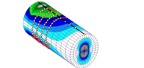
DVCON_AUTO_SHAPE). Then the main node of the symmetry group is
determined and the displacements of the client nodes are calculated in such a way that
they move rotational symmetric to the axis (see the following figure).
In addition, an angle can be defined to divide the search area into discrete sections:
ANGLE = <real>