Coupling Displacements | ||||||
|
| |||||
| CLIENT / Applicable for | SHAPE_CONTROLLER | SHAPE_SENSITIVITY |
|---|---|---|
| VECTOR | OK | - |
| DIRECTION | OK | - |
| LENGTH | OK | - |
| DISP_CS | OK | - |
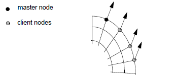
Coupling Displacement Coordinates (VECTOR)
The CLIENT=VECTOR coupling restriction can be used to fully couple a bunch of nodes.
The client nodes inherit both, the direction and the length of the main node.
The following two parameters are entered for coupling displacement coordinates:
CLIENT = VECTOR
CS     = name_of_coord_system
The procedure involves calculating the difference between the current coordinates and start
coordinates of the main node in relation to the coordinate systems referenced by
CS. Then the start coordinates of the client nodes are
calculated in relation to the coordinate system, the difference of the main node is
applied, and the current coordinates of the client nodes are determined (see the
following figure).
 |
It is also possible to couple only single displacement coordinates
by adding options to the standard form of the CLIENT=VECTOR
parameter:
CLIENT = VECTOR, ON/OFF, ON/OFF, ON/OFF
CS     = name_of_coord_system
Each of the three coordinates can be set to either ON
or OFF. Only the displacement coordinates set to
ON are coupled. Displacement coordinates set to OFF
are not taken into consideration for the coupling. The default setting
is VECTOR=ON, ON, ON.
Important:
|
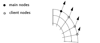
Coupling Displacement Direction (DIRECTION)
In contrast to the above CLIENT = VECTOR coupling restriction, this one can be used to couple only the directions. But every node can stay with individual lengths.
The following two parameters are entered for coupling the displacement direction:
CLIENT = DIRECTION
CS     = name_of_coord_system
The procedure is the same as that for CLIENT=VECTOR,
but with the difference that the retained displacement vector is rescaled
to the original displacement amount of the client nodes (see the following
figure).
 |
Important:
|
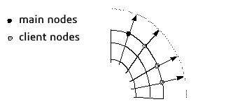
Coupling Amount of Displacement (LENGTH)
In contrast to the above CLIENT = VECTOR coupling restriction, this one can be used to couple only the optimization length. But every node can stay with individual directions.
The following parameter is entered for coupling the amount of displacement:
CLIENT = length
The procedure is as follows: The amount of displacement of the main node is calculated and the displacement direction of the main node is determined (growth or shrinkage). The displacements of the client nodes are scaled in such a way that the displacement amount of the main node is retained (see the following figure).
 |
Coupling Coordinates in the FE Displacement Coordinate System (DISP_CS)
The nodes are fully coupled like with the CLIENT=VECTOR restriction,
but the nodes are moved in their local coordinate system.
The following parameter is entered for coupling the coordinates in the FE displacement coordinate system:
CLIENT = DISP_CS
The procedure is as follows: The optimization displacements (coordinates)
of the main node with reference to the FE displacement coordinate system
are transferred directly into the FE displacement coordinate system of
the client nodes. It is also possible to couple only single displacement
coordinates by adding parameters to the standard form of the CLIENT=DISP_CS
parameter
CLIENT = DISP_CS, ON/OFF, ON/OFF, ON/OFF
Each of the three coordinates can be set to either ON
or OFF. Only the displacement coordinates set to
ON are coupled. Displacement coordinates set to OFF
are not taken into consideration for the coupling. The default setting
is DISP_CS, ON, ON, ON.
Important:
|