-
Define input data and Design Variables:
FEM_INPUT
  ID_NAME  = INPUT_FILE
  FILE     = upright_mimp.inp
END_

DV_TOPO
  ID_NAME  = globalDesignArea
  EL_GROUP = "Design_Space1"
END_
-
Define additional groups by combining (LIST_GROUP) and subtracting (LIST_SUBTRACT_GROUP) existing groups:
GROUP_DEF
  ID_NAME = globalFrozenRegion
  TYPE    = ELEM
  FORMAT  = LIST_GROUP
  LIST_BEGIN
"Functional Region1",
"Functional Region2",
"Functional Region3",
"Functional Region4",
"Functional Region5",
"Functional Region7",
"Functional Region8"
END_

GROUP_DEF
  ID_NAME = designAreaNonFrozen
  TYPE    = ELEM
  FORMAT  = LIST_SUBTRACT_GROUP
  LIST_BEGIN
"Design_Space1", globalFrozenRegion
END_
-
To use mass in the objective, define a Design Response (DRESP) as follows:
DRESP
  ID_NAME    = TASK_MASS
  DEF_TYPE   = SYSTEM
  TYPE       = WEIGHT
  EL_GROUP   = "Design_Space1"
  GROUP_OPER = SUM
END_
-
Define the Objective Function (OBJ_FUNC) as follows:
OBJ_FUNC
  ID_NAME = MY_OBJECTIVE
  DRESP   = TASK_MASS
  TARGET  = MIN
END_
-
To define the stress, displacement and frequency constraints, do the following:
-
Define the corresponding design responses (Here, one DRESP each for stress and displacement is shown instead of the total 4):
DRESP
  ID_NAME  = StressConstraint1_LC1
  DEF_TYPE = SYSTEM
  TYPE     = SIG_TOPO_MISES
  EL_GROUP = designAreaNonFrozen
  LC_SET   = ALL,1,ALL
END_

DRESP
  ID_NAME  = DisplacementConstraint1_LC1
  DEF_TYPE = SYSTEM
  TYPE     = DISP_ABS
  ND_GROUP = "Displacement Constraint6"
  LC_SET   = ALL,1,ALL
END_

DRESP
  ID_NAME  = eig1
  DEF_TYPE = SYSTEM
  TYPE     = DYN_FREQ
  UPDATE   = EVER
  LC_SET   = MODAL,3,1
END_
-
Define the respective stress, displacement and frequency constraints (CONSTRAINT)
(Here, one CONSTRAINT each for stress and displacement is shown instead of the total 4):
CONSTRAINT
  ID_NAME   = CONSTRAINT_StressConstraint1_LC1
  DRESP     = StressConstraint1_LC1
  MAGNITUDE = ABS
  LE_VALUE  = 250000000.0
END_

CONSTRAINT
  ID_NAME   = CONSTRAINT_DisplacementConstraint1_LC1_MAX
  DRESP     = DisplacementConstraint1_LC1
  MAGNITUDE = ABS
  LE_VALUE  = 0.00012
END_

CONSTRAINT
  ID_NAME   = FreqCon
  DRESP     = eig1
  MAGNITUDE = ABS
  GE_VALUE  = 100.
END_
-
Define frozen regions (Here, one exemplary DVCON is shown):
DVCON_TOPO
  ID_NAME    = FunctionalRegion1
  CHECK_TYPE = FROZEN
  EL_GROUP   = globalFrozenRegion
END_
-
Reference the Objective Function, Design Variables and Constraints as well as DVCONs in the OPTIMIZE command:
OPTIMIZE
  ID_NAME    = OptimizationTask
  STRATEGY   = TOPO_SENSITIVITY
  DV         = globalDesignArea
  OBJ_FUNC   = OBJECTIVE_MIN_MASS
  CONSTRAINT = CONSTRAINT_StressConstraint1_LC1
  CONSTRAINT = CONSTRAINT_StressConstraint1_LC2
  CONSTRAINT = CONSTRAINT_DisplacementConstraint1_LC1_MAX
  CONSTRAINT = CONSTRAINT_DisplacementConstraint1_LC2_MAX
  CONSTRAINT = FreqCon
  DVCON      = FunctionalRegion
END_
-
Deactivate the function to automatically freeze specific regions and set the minimum initial density to 0.1.
In addition set the material interpolation to MIMP:
OPT_PARAM
  ID_NAME             = OptimizationTask_PARAMS
  OPTIMIZE            = OptimizationTask
  AUTO_FROZEN         = OFF
  MIN_INITIAL_DENSITY = 0.1
  MAT_INTERPOLATION   = MIMP
END_
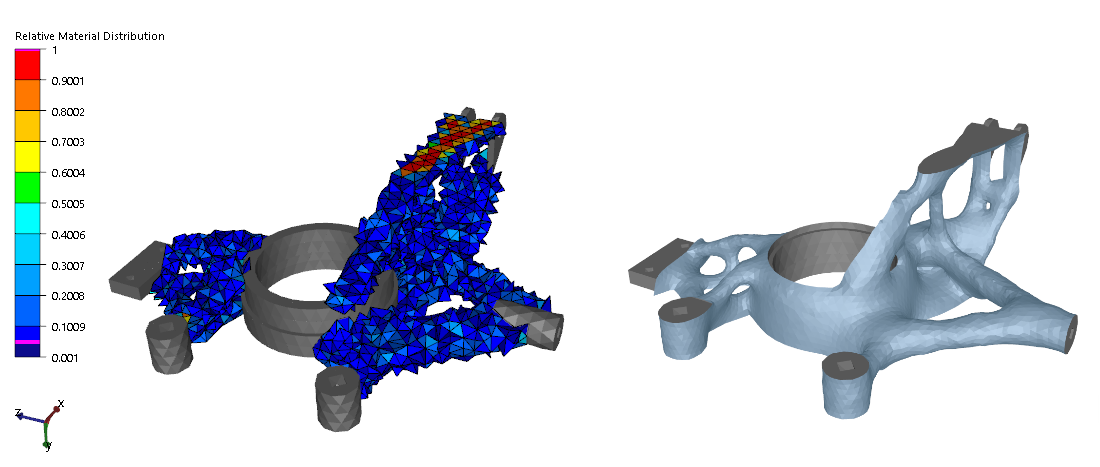
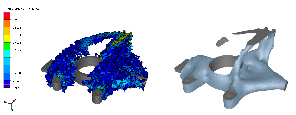
The optimization result looks as follows:
The result using the default interpolation can
be seen below. The structure does not look converged and too much intermediate density is
present. Also, the smoothed result is not valid:
Valid result using the MIMP interpolation. A layer of low density elements is present, but
as in the smoothed image, the structure is well connected and converged: