Linear elastic composites
Elements tested
C3D8R
Features tested
Linear elastic multiscale materials modeled with mean-field homogenization methods.
Problem description
The verification tests consist of a set of single-element tests that use C3D8R elements under mechanical and thermal loading conditions. All constituents of the composite material are linear elastic. Material properties including Young's modulus, and Poisson's ratio, are listed below. Microstructure properties including volume fraction, and aspect ratio, are also listed.
Material:
- Composite 1
-
Matrix properties:
250 GPa 0.3 80% Inclusion one properties:
750 GPa 0.3 10% infinite Inclusion two properties:
1000 GPa 0.3 10% infinite Both inclusions are cylindrical and aligned.
- Composite 2
-
Matrix properties:
3.16 GPa 0.35 Inclusion properties:
73.1 GPa 0.18 1.0 The inclusions are spherical with variable volume fractions.
- Composite 3
-
Matrix properties:
70 GPa 0.33 Inclusion properties:
300 GPa 0.2 10% 20.0 The shape of the inclusion is prolate, and the inclusions are aligned.
- Composite 4
-
Matrix properties:
4.5 GPa 0.38 Inclusion properties:
172 GPa 0.2 0.04 The inclusion is penny-shaped and randomly oriented in 3D.
- Composite 5
-
The material properties are the same as those for Composite 4, but the inclusion directions are specified with a different second-order orientation tensor,
- Composite 6
-
Matrix properties:
3 GPa 0.35 CTE 70e-6 Inclusion properties:
172 GPa 0.2 CTE 1e-6 The volume fraction and aspect ratio of the inclusion are variable.
- Composite 7
-
Matrix properties:
3.45 GPa 0.35 Inclusion properties:
73.1GPa 0.22 The inclusion is continuous fiber (cylinder-shaped).
- Composite 8
-
Matrix properties:
5.35 GPa 0.354 Inclusion properties (transversely isotropic):
232 GPa 15 GPa 0.279 0.49 24 GPa The inclusion is continuous fiber (cylinder-shaped).
Results and discussion
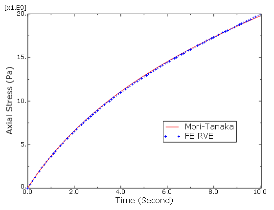
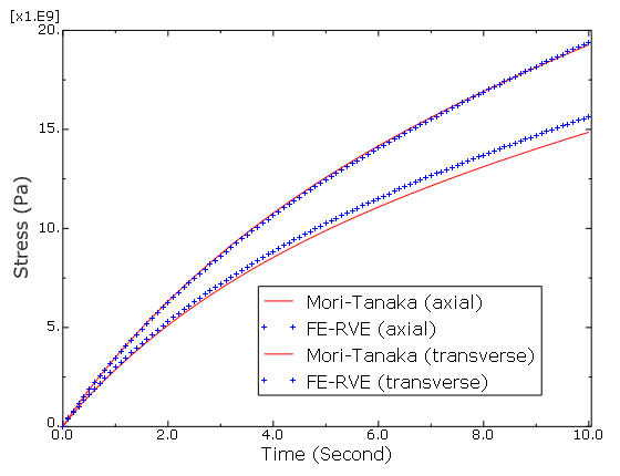
A two-step mean-field homogenization method is used to obtain the transverse response of Composite 1. Both Mori-Tanaka and the balanced homogenization model are used in Step 1, and Voigt homogenization is used in Step 2. Results are compared with the FE-RVE prediction in Table 1. The mean-field predictions show good agreement with the FE-RVE results.
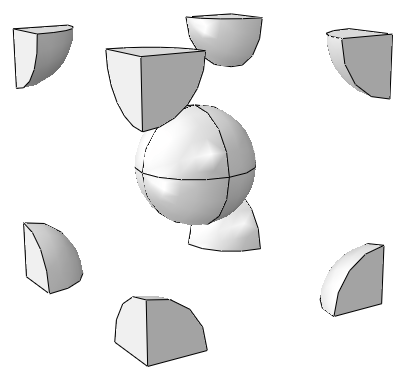
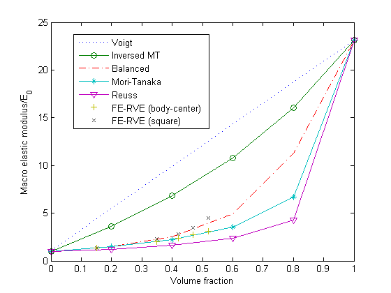
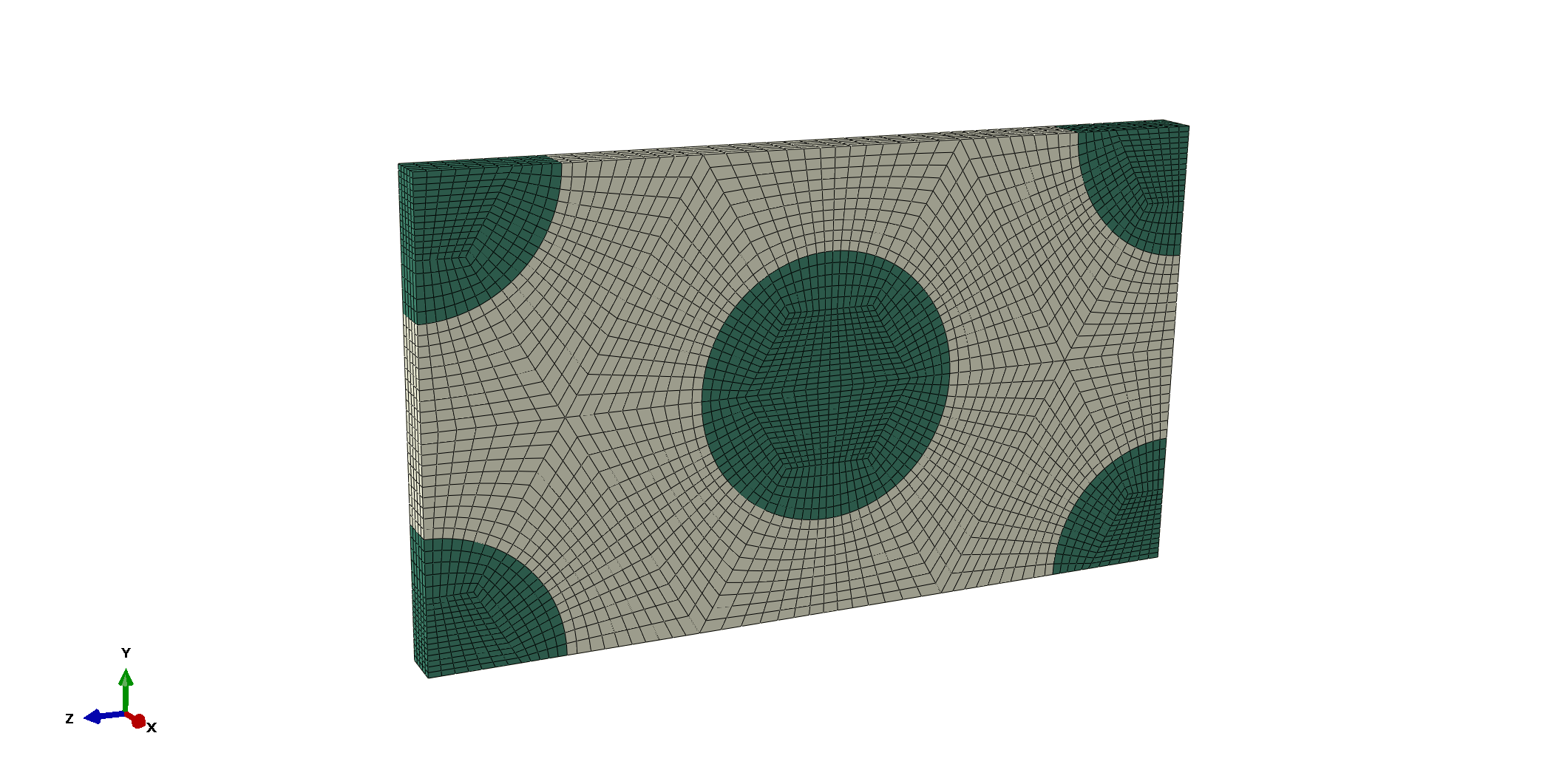
The influence of the volume fraction on the normalized macroscale modulus of Composite 2 is plotted in Figure 2 using various homogenization methods. Two different FE-RVEs are used for comparison: body-centered and square packed. The body-centered FE-RVE is shown in Figure 1. The square-packed FE-RVE is also a cubic cell with only a single sphere in the middle of the cell. The Mori-Tanaka prediction matches the body-centered FE-RVE prediction very well, while the balanced prediction matches the square-packed FE-RVE results very well up to a volume fraction of 50%. Interaction between inclusions is stronger in the squared-packed FE-RVE compared to the body-centered FE-RVE, which can be better captured with the balanced method.
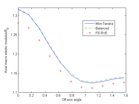
Composites with various off-axis angles are tested with Composite 3. The influence of the off-axis angle on the normalized macroscale modulus in the traction direction is plotted in Figure 3. Mori-Tanaka and the balanced homogenization methods are used, and the predicted macroscale properties compare well with the FE-RVE results. The body-centered FE-RVE model is used to obtain the stiffness modulus of the composite through a linear perturbation step as described above. The engineering constants predicted by the FE-RVE model are listed in Table 2, with the 1-direction being the inclusion direction. The axial macroscale elastic modulus is then computed at all off-axis angles through transformation.
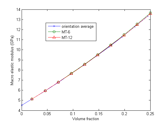
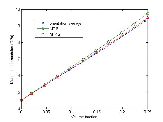
The influence of the volume fraction on the macroscale elastic modulus of Composite 4 in the traction direction is plotted in Figure 4. 6 × 6 angle subdivisions and 12 × 12 angle subdivisions are used for the numerical integration over the orientations. Two-step homogenization is used; Mori-Tanaka homogenization is used in Step 1, and Voigt homogenization is used in Step 2. For comparison, the macroscale elastic modulus is also computed directly using the orientation average,
The same studies are made with Composite 5, and the results are plotted in Figure 5. The predicted macroscale modulus matches well with the orientation average.
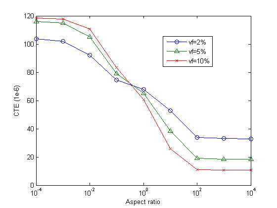
Thermal-elastic composites under thermal loading are also tested with Composite 6. The influence of aspect ratio on the predicted macroscale coefficient of thermal expansion (CTE) is plotted in Figure 6.
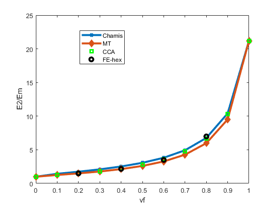
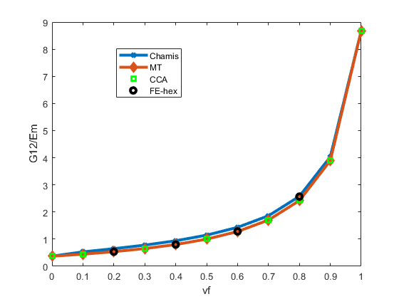
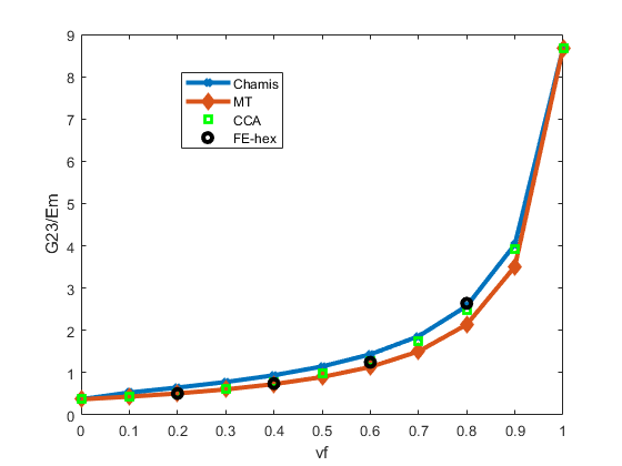
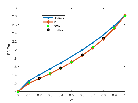
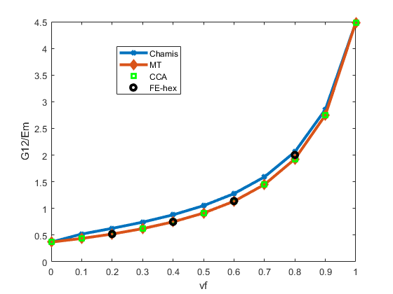
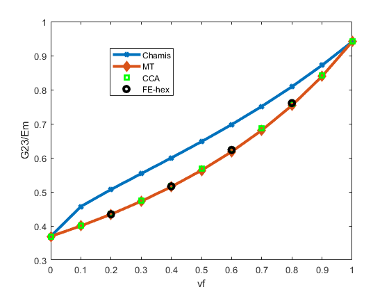
A comparison of homogenized elastic constants is performed for Composites 7 and 8. Both are UD composites with continuous fibers. The fiber material in Composite 7 is isotropic glass fiber, and the fiber material in Composite 8 is transversely isotropic carbon fiber. The homogenized elastic properties are transversely isotropic, and the 1-direction is the fiber direction, which is also the 1-direction of the local direction of the fiber. We compared the homogenized elastic constants computed using Chamis, CCA and Mori-Tanaka formulations with FE-RVE results at various volume fractions. The fibers in the FE-RVEs are hex packed, as shown in Figure 7. The homogenized constants and are very close between all results. Therefore, only and and are shown in the figures. Results for epoxy-glass Composite 7 are shown in Figure 8, Figure 9 and Figure 10. We can see that the homogenized results compare well with FE-RVE results, with Chamis and CCA slightly better than Mori-Tanaka at high volume fractions. Results for epoxy-carbon Composite 8 are shown in Figure 11, Figure 12 and Figure 13. The results based on Chamis formulation show the largest deviation compared to FE-RVE results, while both CCA and Mori-Tanaka compare well with FE-RVE results for all volume fractions.
Input files
- multscale-twostep-mt.inp
- One-element test using Composite 1 with two-step mean-field homogenization. Mori-Tanaka homogenization is used in the first step, and Voigt homogenization is used in the second step.
- multscale-twostep-balanced.inp
- One-element uniaxial tension test using Composite 1. Traction is applied in the transverse direction. Two-step mean-field homogenization is used. Balanced homogenization is used in the first step, and Voigt homogenization is used in the second step.
- multscale-onestep.inp
- One-element uniaxial tension test using Composite 1. Traction is applied in the transverse direction. Direct Mori-Tanaka homogenization is used, which is equivalent to using Mori-Tanaka homogenization in both the first and second step.
- rve-twocylinder.inp
- FE-RVE model of Composite 1 under transverse loading.
- multscale-sphere-vf.inp
- One-element uniaxial tension tests using Composite 2 with various volume fractions and homogenization methods.
- multscale-sphere-vf2.inp
- One-element uniaxial tension tests using Composite 2 with various volume fractions and homogenization methods.
- rve-sphere-vf10-bc.inp
- FE-RVE model of Composite 2 with a volume fraction of 10% under uniaxial tension loading. Inclusions are packed with a body-centered pattern.
- rve-sphere-vf10-sq.inp
- FE-RVE model of Composite 2 with a volume fraction of 10% under uniaxial tension loading. Inclusions are packed with a square pattern.
- multscale-angle-mt.inp
- One-element uniaxial tension tests using Composite 3 with various off-axis angles specified with fixed inclusion directions. Mori-Tanaka homogenization is used.
- multscale-angle-balanced.inp
- One-element uniaxial tension tests using Composite 3 with various off-axis angles specified with fixed inclusion directions. Balanced homogenization is used.
- rve-prolate-vf10.inp
- FE-RVE model of Composite 3 under uniaxial tension loading. Inclusions are packed with a body-centered pattern and aligned in the direction of the traction.
- multscale-penny-random3d-6.inp
- One-element uniaxial tension test using Composite 4. Mori-Tanaka homogenization is used; 6 × 6 angle divisions are used for numerical integration.
- multscale-penny-random3d-12.inp
- One-element uniaxial tension test using Composite 4. Mori-Tanaka homogenization is used; 12 × 12 angle divisions are used for numerical integration.
- multscale-penny-oritens-6.inp
- One-element uniaxial tension test using Composite 5 with dispersed inclusion orientations specified with a second-order orientation tensor. Mori-Tanaka homogenization is used; 6 × 6 angle divisions are used for numerical integration.
- multscale-penny-oritens-12.inp
- One-element uniaxial tension test using Composite 5 with dispersed inclusion orientations specified with a second-order orientation tensor. Mori-Tanaka homogenization is used; 12 × 12 angle divisions are used for numerical integration.
- multscale-cte-vf2.inp
- One-element tests using Composite 6 under thermal loading. Various aspect ratios are used for the inclusions. Mori-Tanaka homogenization is used. The volume fraction of the inclusion is 2%.
- multscale-cte-vf5.inp
- One-element tests using Composite 6 under thermal loading. Various aspect ratios are used for the inclusions. Mori-Tanaka homogenization is used. The volume fraction of the inclusion is 5%.
- multscale-cte-vf10.inp
- One-element tests using Composite 6 under thermal loading. Various aspect ratios are used for the inclusions. Mori-Tanaka homogenization is used. The volume fraction of the inclusion is 10%.
References
- “Mean-Field Homogenization of Multi-Phase Thermo-Elastic Composites: a General Framework and its Validation,” Composites Science and Technology, vol. 64, pp. 1587–1603, 2004.
- “The Use of Tensors to Describe and Predict Fiber Orientation in Short Fiber Composites,” Journal of Rheology, vol. 31(8), pp. 751–784, 1987.
- “Representation of Mechanical Behavior in the Presence of Changing Internal Structure,” Journal of Applied Mechanics, vol. 55(1), pp. 1–10, 1988.
Tables
| Method | Mori-Tanaka/Voigt | Balanced/Voigt | Mori-Tanaka/Mori-Tanaka | FE-RVE |
|---|---|---|---|---|
| 1.2340 | 1.2408 | 1.2340 | 1.2412 |
| 1.28 | 1.130 | 1.13 | 0.316 | 0.316 | 0.347 | 0.421 | 0.421 | 0.417 |
Figures