Designing the mesh: partitioning and creating the mesh
You need to consider the type of element that will be used before
you start building the mesh for a particular problem.
For example, a suitable mesh design that uses quadratic elements
may very well be unsuitable if you change to linear, reduced-integration
elements.
For this example use 20-node hexahedral elements with reduced integration (C3D20R). Once you have selected the element type, you can design the
mesh for the connecting lug. The most important decision regarding the mesh
design for this example is how many elements to use around the circumference of
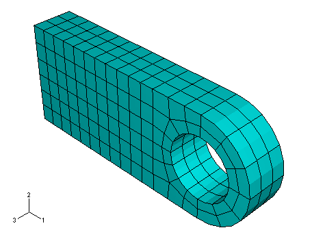
the lug's hole. A possible mesh for the connecting lug is shown in
Figure 1.
Figure 1. Suggested mesh of C3D20R elements for the connecting lug model.
Another thing to consider when designing a mesh is the type of results you
want from the simulation. The mesh in
Figure 1
is rather coarse and, therefore, unlikely to yield accurate stresses. Four
quadratic elements per 90° is the minimum number that should be considered for
a problem such as this one; using twice that many is recommended to obtain
reasonably accurate stress results. However, this mesh should be adequate to
predict the overall level of deformation in the lug under the applied loads,
which is what you were asked to determine. The influence of increasing the mesh
density used in this simulation is discussed in
Mesh convergence.
Abaqus/CAE
offers a variety of meshing techniques to mesh models of different topologies.
The different meshing techniques provide varying levels of automation and user
control. The following three types of mesh generation techniques are available:
Structured meshing
Structured meshing applies preestablished mesh patterns to particular model
topologies. Complex models must generally be partitioned into simpler regions
to use this technique.
Swept
meshing
Swept meshing extrudes an internally generated mesh along a sweep path or
revolves it around an axis of revolution. Like structured meshing, swept
meshing is limited to models with specific topologies and geometries.
Free
meshing
The free meshing technique is the most flexible meshing technique. It uses
no preestablished mesh patterns and can be applied to almost any model shape.
Bottom-up
meshing
You use the bottom-up meshing technique to create a hexahedral or
hex-dominated mesh on a solid region that is unmeshable or difficult to mesh
using the automated top-down meshing techniques. Bottom-up meshing is a manual
process that allows you to select the method and parameters that
Abaqus/CAE
uses to build up a solid mesh of hexahedral elements. Bottom-up meshing is not
discussed in any of the examples in this guide.
When you enter the
Mesh module,
Abaqus/CAE
color codes regions of the model according to the methods it will use to
generate a mesh:
Green indicates that a region can be meshed using structured methods.
Yellow indicates that a region can be meshed using sweep methods.
Pink indicates that a region can be meshed using the free method.
Tan indicates that the region can be meshed using the bottom-up method.
Orange indicates that a region cannot be meshed using the default
element shape assignment and must be partitioned further.
Dependent part instances are colored blue at the assembly level. You must
switch to a part-level view to mesh a dependent part instance.
In this problem you will create a structured mesh. You will find that the
model must first be partitioned further to use this mesh technique. After the
partitions have been created, a global part seed will be assigned and the mesh
will be created.
Partition the lug
In the
Model Tree,
expand the Lug item underneath the
Parts container and double-click Mesh
in the menu that appears.
The part is colored yellow initially, indicating that with the
default set of mesh controls, a hexahedral mesh can be created only using a
swept mesh technique. Additional cell partitions are required to permit
structured meshing. Two partitions will be created. The first partition permits
structured meshing to be used, and the second improves the overall quality of
the mesh.
Note:
The Object field that appears in the context
bar automatically displays the part so that you can partition the geometry
directly within the
Mesh module.
The ability to switch between individual parts and the model assembly within
the same module is available only in the
Mesh module.
This feature allows you to partition both dependent and independent part
instances in the same module for the purpose of meshing. In all other modules,
partitioning must be done strictly at the part level for dependent instances
(as was done earlier when the pressure load was applied) or at the assembly
level for independent part instances.
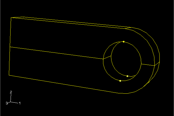
Partition both regions of the lug vertically by defining a cutting
plane through the three points shown in
Figure 2
(use
ShiftClick to
select both regions simultaneously).
Figure 2. First partition to permit structured meshing.
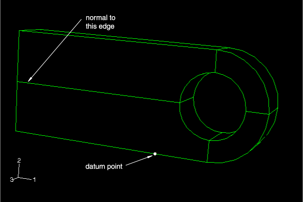
Select
ToolsDatum
from the main menu bar, and create a datum point 0.075 m from the left end of
the lug (as shown in
Figure 3)
using the Offset from point method.
Figure 3. Second partition to improve the mesh quality.
Create the second vertical partition by using the Point
& Normal method to define a cutting plane that is through the
datum point you just created and normal to the centerline of the lug (as shown
in
Figure 3).
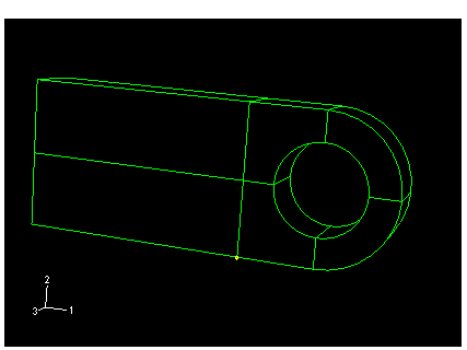
The partitioned lug appears as in
Figure 4.
After you have partitioned the lug, all part regions should be colored green,
which (based on the current mesh controls) indicates structured hexahedral
element meshing will be used everywhere.
Figure 4. Final partitioned lug.
Assign a global part seed and create the mesh
From the main menu bar, select
SeedPart,
and specify a target global element size of
0.007. Seeds appear on all the edges.
From the main menu bar, select
MeshElement
Type to choose the element type for the part.
Because of the partitions you have created, the part is now composed of several
regions.
Use the cursor to draw a box around the entire part and, thus,
select all regions of the part. Click Done in the prompt
area.
In the Element Type dialog box that appears,
select the Standard element library, 3D
Stress family, Quadratic geometric order, and
Hex, Reduced integration element.
Click OK to accept the choice of C3D20R as the element type.
Note:
If you are using the Abaqus Learning Edition, using second-order elements with a global seed size of 0.007
results in a mesh that exceeds the model size limits of the product. Either use
first-order elements (C3D8R) with a
global seed size of 0.007 or second-order elements with a global seed size of 0.01.
From the main menu bar, select
MeshPart.
Click Yes in the prompt area to mesh the part instance.