Visualizing Models and Groups | ||
| ||
-
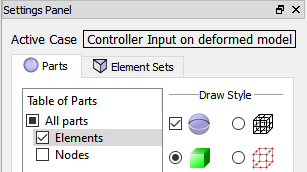
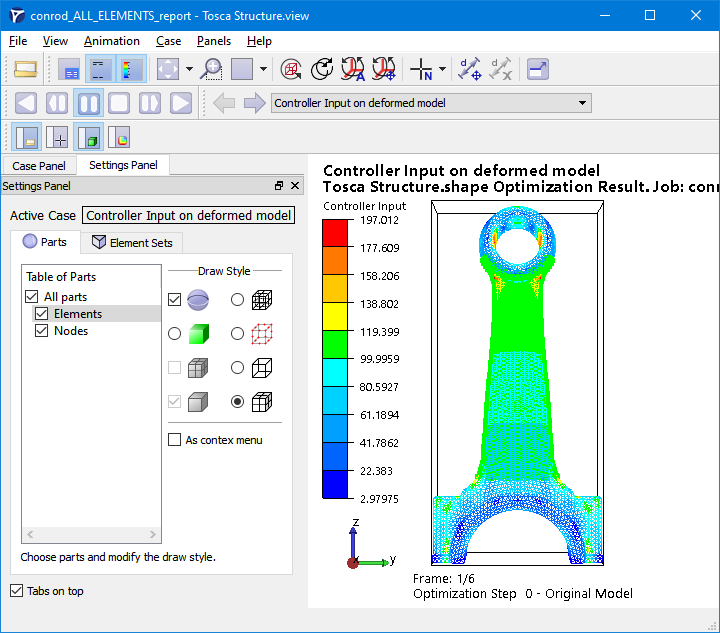
To switch on or off the visibility
of each part, check the box in Settings Panel > Parts tab.
In the following figure, for example, only the Elements part is visible.
-
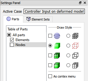
Change the draw style of selected parts (highlighted in Table of Parts) using
the radio buttons on the right side of the selection window. Pressing "Ctrl"-key and left-click you can also select multiple
parts.
In the following figure, for example, the Elements part is visible, but the draw style can only be changed for the Nodes part, because the Elements part is not selected.
-
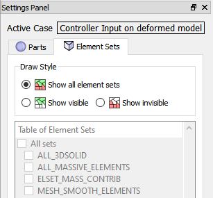
To
visualize a node group, turn on Nodes in the Parts
tab as shown above (it is turned off by default).
In the following example, the design area of shape optimization (a node group DESIGN_NODES) is shown:
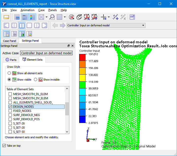
If, additionally, the group ALL_ELEMENTS is chosen
and Draw as lines, with hidden lines removed
in Draw Style panel of the Parts tab is active
for the Elements part, the location of selected nodes is clearly seen:
Groups from the parameter file are presented together with groups from the input finite element model.