Symmetry Conditions (CHECK_LINK) | ||||||||
|
| |||||||
| Applicable for | BEAD_CONTROLLER | BEAD_SENSITIVITY |
|---|---|---|
| POINT_SYM | OK | - |
| PLANE_SYM | OK | OK |
| ROTATION_SYM | OK | - |
| SURF_TURN | - | OK |
Symmetry conditions can also be applied in Tosca Structure.bead. A LINK-condition is required to create a symmetry condition.
The types of symmetry supported by Tosca Structure.bead are point, plane, and rotational symmetry:
bead controller optimization
LINK_BEAD
  ID_NAME = <link_name>
  TYPE    = POINT_SYM
  CS      = <cs_name>
END_
LINK_BEAD
  ID_NAME    = <link_name>
  TYPE       = PLANE_SYM
  CLIENT_DIR = <X_1>, <X_2>, <X_3>
  CS         = <cs_name>
END_
LINK_BEAD
  ID_NAME    = <link_name>
  TYPE       = ROTATION_SYM
  CLIENT_DIR = <X_1>, <X_2>, <X_3>
  CS         = <cs_name>
END_
bead sensitivity optimization
LINK_BEAD
  ID_NAME    = <link_name>
  TYPE       = PLANE_SYM
  CLIENT_DIR = <X_1>, <X_2>, <X_3>
  CS         = <cs_name>
END_
The origin of the coordinate system referenced by the <cs_name> is the
symmetry point or a point on the symmetry plane, where AXIS_* is the normal to this plane. For
rotational symmetry, the origin of the coordinate system is a point on the symmetry axis,
where AXIS_* gives the direction.
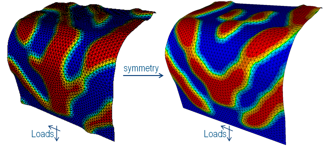
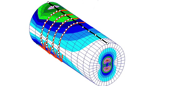
The following figure shows an asymmetric load case without (left) and with (right) symmetry condition:
 |
Important:
|
Point Symmetry (POINT_SYM)
Couple displacements that are symmetric with respect to a point.
This kind of constraint is available only for controller-based optimizations. To couple displacements symmetric to a point, the position of the point must be exactly specified. The following parameters are required for the definition of the link condition:
LINK_BEAD
 ID_NAME = <link_name>
 TYPE    = POINT_SYM, AXIS_*
 CS      = <cs_name>
END_
The origin of the coordinate system referenced by CS defines the symmetry
point. The symmetry of the nodes (assigned by ND_GROUP in the
DVCON_BEAD command) is checked against the symmetry point. Symmetric
nodes are assembled into a symmetry group (usually two symmetric nodes per symmetry group).
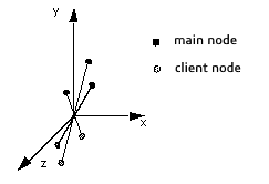
Then the main node of the symmetry group is determined and the displacements of the client
nodes are calculated in such a way that they move symmetric to the point of the main node
(see the following figure).
| Important:
The coordinate system referenced by |
 |
Plane Symmetry (CONTROLLER)
Couple design nodes that are symmetric to a plane - for arbitrary meshes.
This kind of constraint is available only for controller-based optimizations. To couple displacements symmetric to a plane, the position and the orientation of the plane must be specified exactly. Therefore, the plane is created using the coordinate system and an axis normal to the plane. A possible link definition could look like the following:
LINK_BEAD
 ID_NAME    = <link_name>
 TYPE       = PLANE_SYM
 CLIENT_DIR = <X_1>, <X_2>, <X_3>
 CS         = <cs_name>
END_
The symmetry of the nodes (assigned by ND_GROUP in the
DVCON_BEAD command) is checked against the symmetry plane. Symmetric
nodes are assembled into a symmetry group (usually two symmetric nodes per symmetry group).
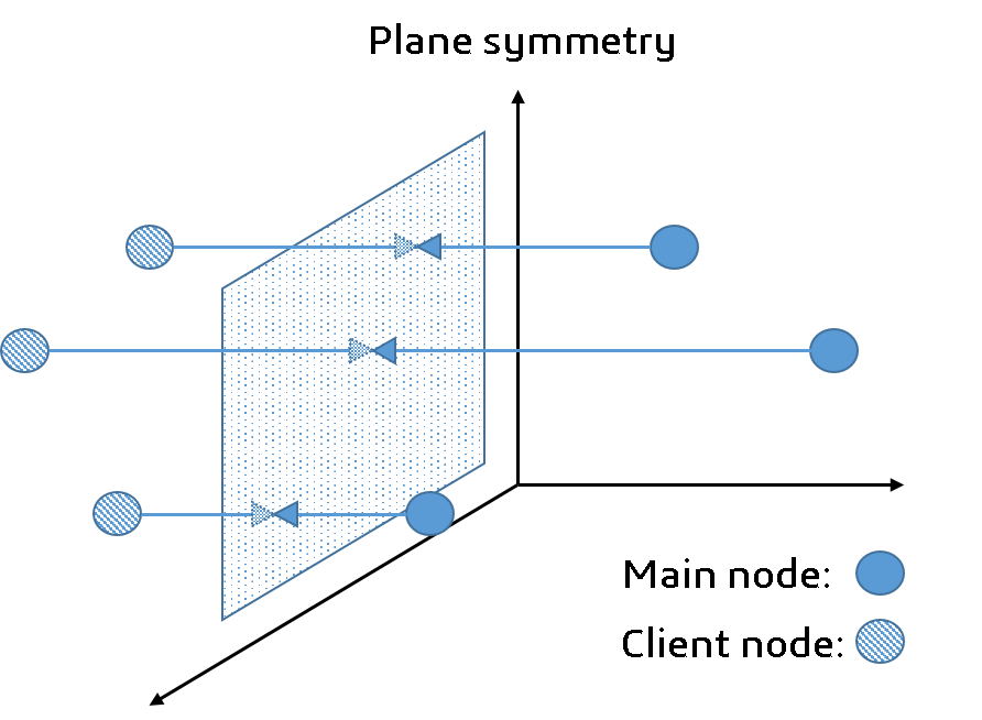
Then the main node of the symmetry group is determined and the displacements of the client
nodes are calculated in such a way that they move symmetrically to the plane of the main
node (see the following figure).
| Important:
|
 |
Plane Symmetry (SENSITIVITY)
Couple design nodes that are symmetric to a plane - for arbitrary meshes.
This kind of constraint is available only for sensitivity-based optimizations. To be able to couple displacements symmetrically to a plane, the position and the orientation of the plane must be specified. This is supported for symmetric and unsymmetric meshed geometries. The following parameters are required for the definition of the link condition:
LINK_BEAD
 ID_NAME    = <link_name>
 TYPE       = PLANE_SYM
 CLIENT_DIR = <X_1>, <X_2>, <X_3>
 CS         = <cs_name>
END_
The origin of the coordinate system referenced by CS defines a point on
the symmetry plane. The direction specified by the PLANE_NORMAL parameter
defines the normal of the plane.
The symmetry of the nodes (assigned by ND_GROUP in the
DVCON_BEAD command) is checked against the symmetry plane. For each node,
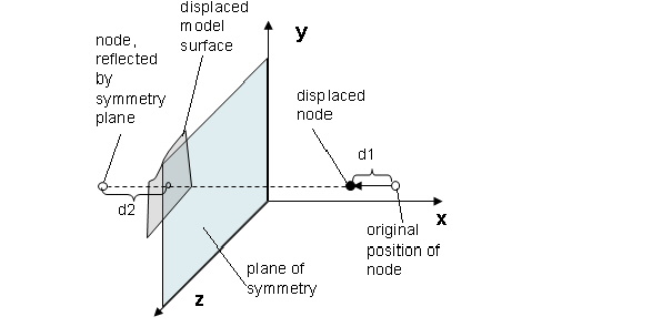
a reference displacement is calculated for its symmetric "counterpart." This counterpart is
obtained by reflecting the node at the symmetry plane; that is, by intersecting a line
through the node in the plane normal direction with the surface defined by all selected
nodes. The reference displacement is obtained by interpolation of the optimization
displacements of the adjacent nodes.
The symmetry is built up using the maximum (default) or the minimum of the displacement of the selected node (d1 in the following figure) and the interpolated displacement of its plane symmetric counter part (reference displacement d2 in the following figure).
 |
Rotational Symmetry (ROTATION_SYM)
Couple displacements that are rotational symmetric around an axis.
This kind of constraint is available only for controller-based optimizations. To couple displacements rotationally symmetric about an axis, the position and the orientation of the axis must be specified exactly. The mesh of the coupled node group should be rotational symmetric. These parameters are specified as follows:
LINK_BEAD
  ID_NAME = <link_name>
  TYPE    = ROTATION_SYM, AXIS_*
  CS      = <cs_name>
  ANGLE   = <value>
END_
The origin of the coordinate system referenced by CS defines a point on the axis. The
direction specified by the AXIS* parameter defines the axis direction. The
symmetry of the nodes assigned by ND_GROUP in the
DVCON_BEAD command is checked against the symmetry axis. Symmetric nodes
are assembled into a symmetry group, a simplification of the GROUP_AUTO_DEF
command, where these symmetry groups can be build according to cylindrical coordinate
systems. Then the main node of the symmetry group is determined and the displacements of the
client nodes are calculated in such a way that they move rotational symmetric to the axis
(see the following figure).
 |
In addition, an angle can be defined to divide the search area into discrete sections.
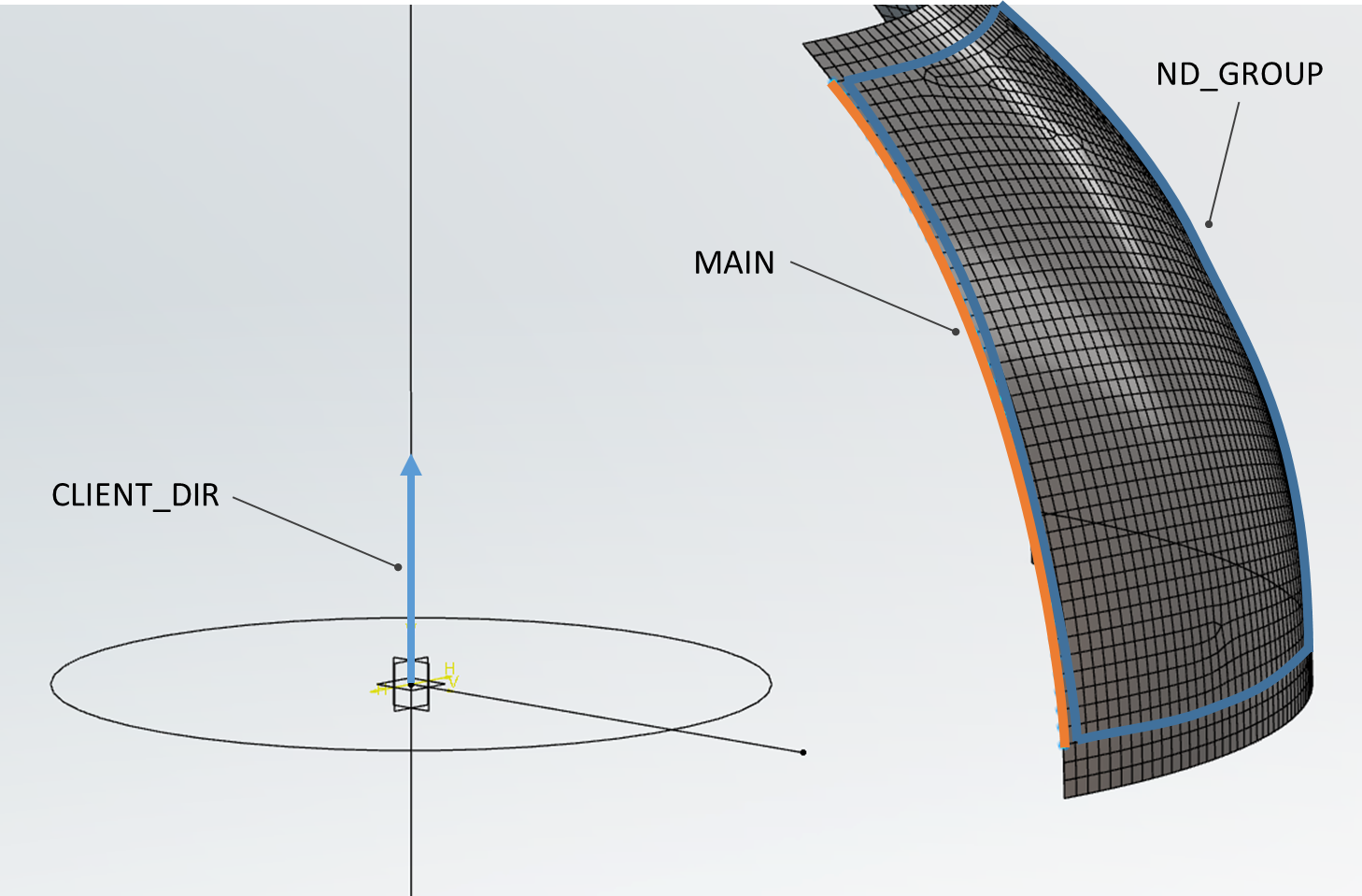
Rotational Symmetry (SURF_TURN, SENSITIVITY)
BEAD_SENSITIVITYThe SURF_TURN manufacturing constraint for sensitivity-based bead
optimization can be used to achieve a turnable or rotational symmetric surface.
The important parameters are the rotational axis CLIENT_DIR, together with
the origin, specified by a coordinate system CS. Next, the specification of
"driving" area (MAIN) is a required part of the setup.
The link condition is defined using the following parameters and is visualized in the figure below:
LINK_BEAD
  ID_NAME    = <link_name>
  TYPE       = SURF_TURN
  CS         = <cs_name>
  CLIENT_DIR = <X_1>, <X_2>, <X_3>
  MAIN       = NDGR, <main_node_group>
END_
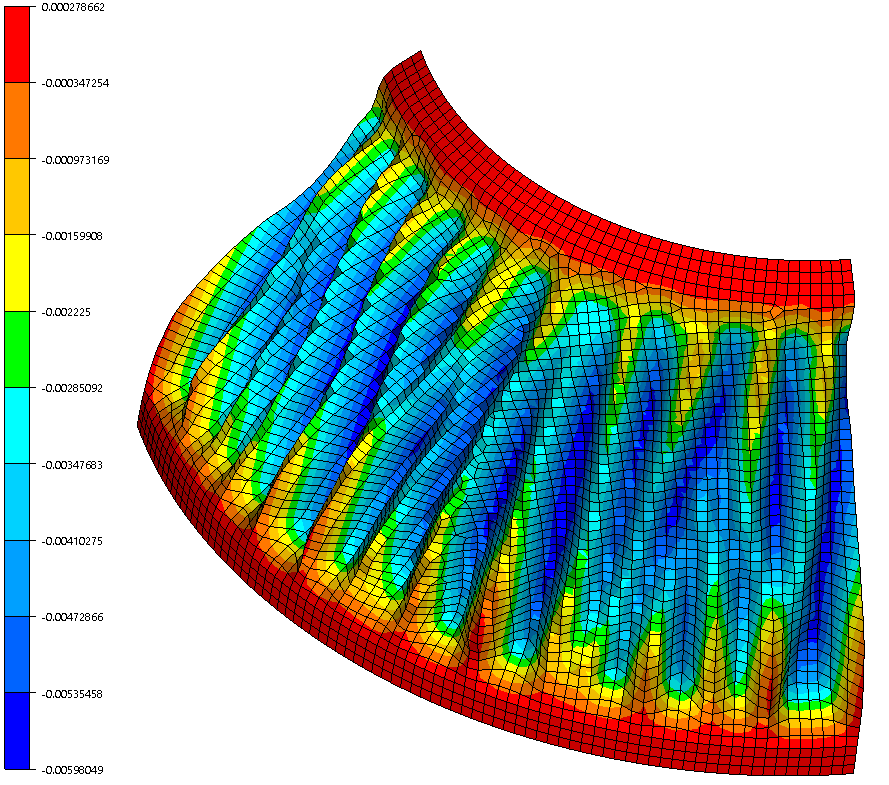
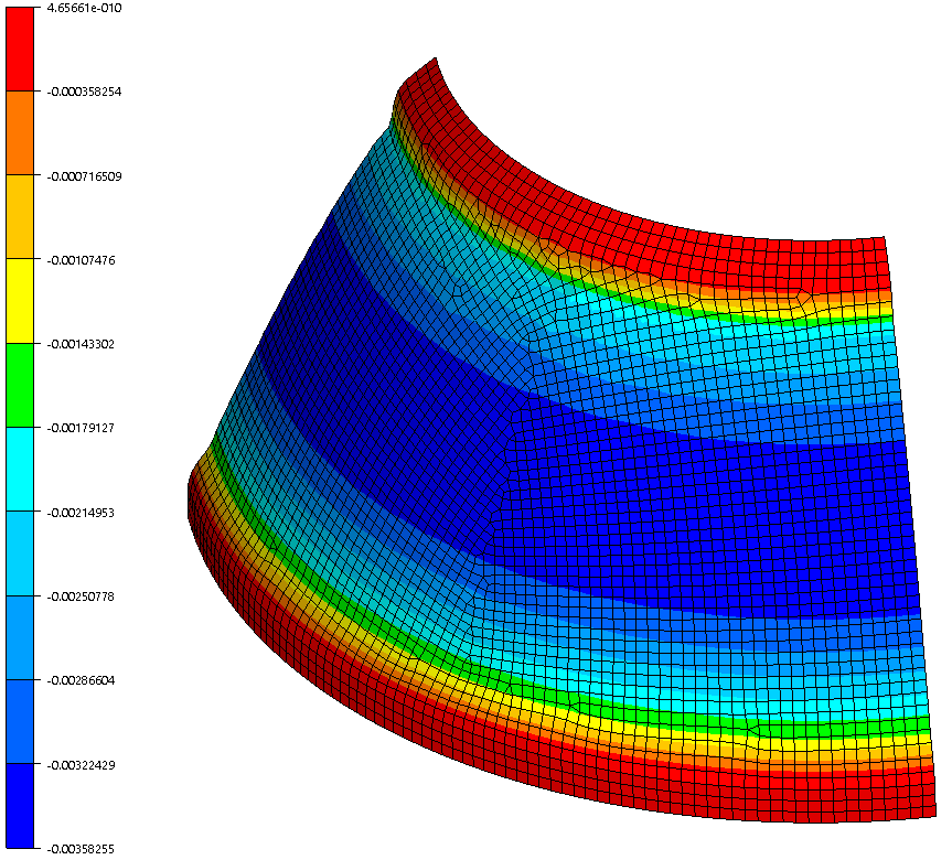
These two figures show the effect of this manufacturing constraint. The left figure has the control deactivated, while it is active in the right one.
 |
 |
Important:
|