CFD Model | ||
| ||
Mesh
In the figure below, the fluid mesh of the CFD model is depicted:
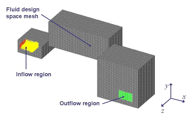
The mesh is made up of three adjacent boxes and consists of 400.896 hexahedron cells.
Boundaries
A boundary region providing inflow is located at the small box on the left. An outflow boundary condition is located on the right. The table below holds the properties for the two boundary regions:
Inflow region |
|
Boundary type |
Inlet |
Velocity u, v, w [m/s] |
3.0, 0.0, 0.0 |
Turbulence intensity |
0.05 |
Characteristic length [m] |
0.001 |
Density [kg/m³] |
1.205 |
Outflow region |
|
Boundary type |
Outlet |
Flow split |
1 |
Solution Parameters
The standard material model for air is selected together with a k-epsilon High Reynolds number turbulence model (default parameters).
The solution method is set to steady state. (scalar solver, CG method).
Cell Types
For this optimization problem, the complete fluid mesh is used as design space. Therefore, all cells are used as design cells in SIMULIA Tosca Fluid and hence are all assigned to the same cell region.