Damage Evolution
Damage Initiation for Fiber-Reinforced Composites Using Multiscale Modeling discussed the constituent-level damage initiation in fiber-reinforced composites. This section discusses the post-damage initiation behavior for cases in which a damage evolution model has been specified. The damage evolution is modeled at the constituent level, leading to the damage process of a composite through homogenization. Prior to damage initiation, the constituent material is linearly elastic, with the stiffness matrix of an isotropic or a transversely isotropic material. Thereafter, the response of the constituent material is computed from
The damage variables, , are derived from damage variables in each constituent based on tension or compression modes, as follows:
- Fiber:
-
- Matrix:
-
Evolution of Damage Variables for Each Mode
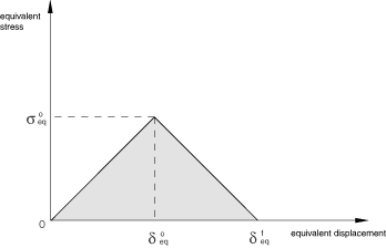
To alleviate mesh dependency during material softening, Abaqus introduces a characteristic length into the formulation so that the constitutive law is expressed in a stress-displacement relation. The damage variable evolves such that the stress-displacement behaves as shown in Figure 1 in each of the two failure modes (tension and compression). The positive slope of the stress-displacement curve before damage initiation corresponds to linear elastic material behavior; the negative slope after damage initiation is achieved by evolution of the respective damage variables according to the equations shown below.
The equivalent displacement and stress for the tension and compression damage modes are defined as follows:
Tension with the HSNFIBER damage criterion:
Compression with the HSNFIBER damage criterion:
Tension with the HSNMATRIX or TSINVMATRIX damage criterion:
where and are the maximum principal stress/strain in the plane normal to the fiber direction.
Compression with the HSNMATRIX or TSINVMATRIX damage criterion:
where and are the minimum principal stress/strain in the plane normal to the fiber direction.
The characteristic length, , is based on the element geometry and formulation. is a typical length of a line across an element for a first-order element and half of the same typical length for a second-order element. For membranes and shells, is a characteristic length in the reference surface, computed as the square root of the area. The symbol in the equations above represents the Macaulay bracket operator, which is defined for every as .
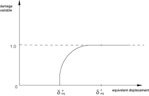
After damage initiation (that is, ) for the behavior shown in Figure 1, the damage variable for a particular mode is given by the following expression:
The values of for the various modes depend on the elastic stiffness and the strength parameters specified as part of the damage initiation definition (see Damage Initiation for Fiber-Reinforced Composites). For each failure mode, you must specify the energy dissipated by failure, , which corresponds to the area of the triangle OAC in Figure 3.
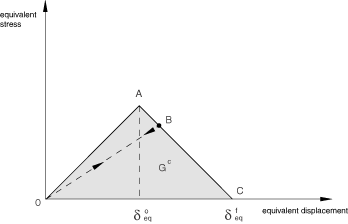
The values of for the various modes depend on the respective values.
Unloading from a partially damaged state, such as point B in Figure 3, occurs along a linear path toward the origin in the plot of equivalent stress versus equivalent displacement. This same path is followed back to point B on reloading as shown in the figure.
Input File Usage
Use the following option to define the damage evolution law:
DAMAGE EVOLUTION, TYPE=ENERGY, SOFTENING=LINEAR ,
where , are energies dissipated during damage for tension and compression failure modes, respectively.
You can specify the post-damage residual stiffness scaling factor directly for the tension and compression failure modes. The scaling factor is related to the damage variable as
Input File Usage
Use the following option to define the post-damage residual stiffness scaling factor directly for damage evolution:
DAMAGE EVOLUTION, TYPE=DISCONTINUOUS ,
where and are the post-damage scaling factor for tension and compression failure modes, respectively.