About Design Variables (DV_SHAPE) | |||||||
|
| ||||||
| Important:
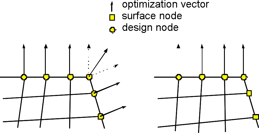
Only surface nodes are allowed as design nodes.
|
Strictly speaking, design variables are the signed amounts of optimization displacement applied to the design nodes. In unrestricted tasks, the direction of the optimization displacement vector corresponds to the outer surface unit normal on the node and the amount of displacement is determined by the optimization procedure. Restrictions influence the amount and direction of the optimization displacement vector.
Basically there are three cases that might occur:
- Growth means that a design node is moved outwards (positive amount of displacement).
- Shrinkage means that a design node is moved inwards (negative amount of displacement).
- Neutral means that a design node is moved neither outwards nor inwards (zero displacement).
| Important:
The optimization displacement vector contains the optimized changes in positions of the nodes and not the displacements of the nodes obtained from the FE analysis. When unrestricted design nodes lie in component areas in which they have only a little mechanical effect on the system as a whole, an undesirable “shrink effect” might occur. Therefore, design areas should not be selected before the mechanical component behavior is known. It is recommended to analyze the mechanical behavior of the component in a preliminary FE calculation before specifying the design area. |
Determination of Optimization Displacement Vectors
- The optimization displacement vector on the design node is determined
by superimposing all external element normal vectors on the boundaries
of neighboring elements. In two-dimensional models the normals are formed
relative to element edges and in three-dimensional to element surfaces.
The only element edges or element surfaces that are taken into consideration
are those spanning design nodes. Isolated
design nodes (neighboring nodes on the surface are not design nodes)
are not permitted and must be removed from the design node group. The
optimization displacement direction is a uniform vector.
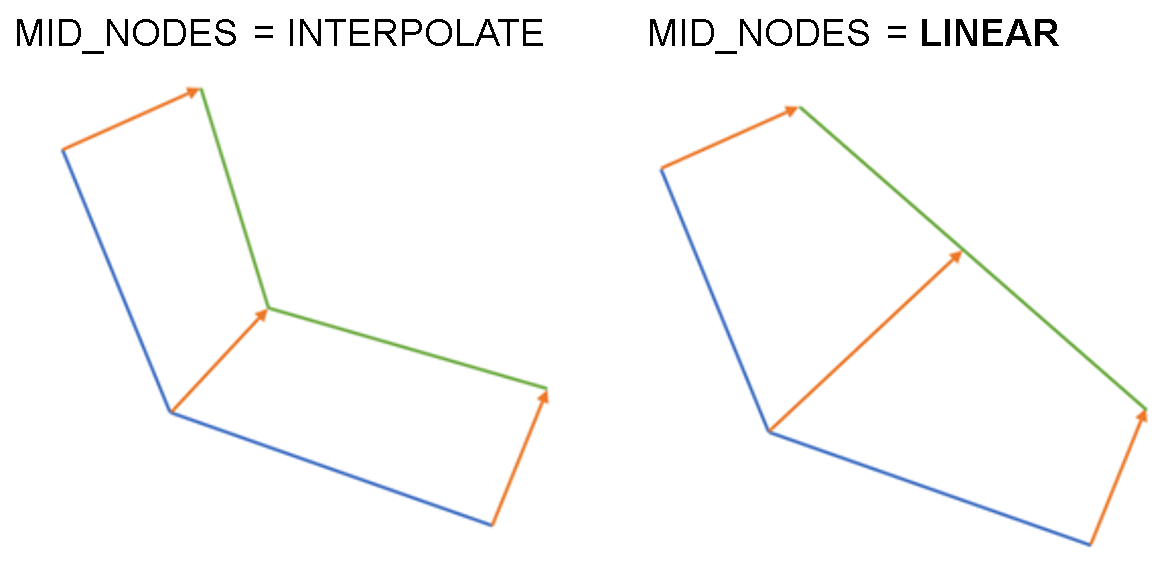
Example:
In a two-dimensional model each design node has two neighboring nodes on the boundary of the component. If both of these neighboring nodes are design nodes, see the figure above on the left, two normal vectors are formed, one each for the respective element edges, and superimposed. If only one of the neighboring nodes is a design node, see the figure above on the right, there is only one normal vector. This is identical with the normal vector of the design node.
- If the displacement direction of a node is restricted
by a design variable constraint (
DVCON_SHAPE), the direction of the optimization displacement vectors is correspondingly adjusted. - The optimization displacement vector is derived from scaling the optimization displacement direction with the signed amount of displacement calculated by the optimization procedure.
- The length of the optimization displacement vector might also be influenced
by design variable constraints (
DVCON_SHAPE).
- The optimization displacement vector determined by the optimizer is adjusted to the changed conditions in each design cycle (for example, shape of the structure, effective restrictions, mesh quality, etc.). The optimization displacement vectors are therefore not constant; they are subject to certain changes in each cycle.
- With the
VECTORparameter in the optimization settings (commandOPT_PARAM), it is possible to control when the optimization displacement vectors are calculated.
Supported Elements Attached to Shape Sensitivity Design Nodes Using SENS_CALC_MODE = SOLVER with Abaqus.
Valid element types for sensitivity-based nodal optimization with Abaqus sensitivities. |
Abaqus element type |
PLANE_QUAD_4 |
CPE4 CPE4R |
PLANE_QUAD_4 |
CPEG4 CPEG4R |
PLANE_QUAD_4 |
CPS4 CPS4R |
PLANE_QUAD_8 |
CPEG8 CPEG8R |
PLANE_QUAD_8 |
CPS8 CPS8R |
PLANE_QUAD_8 |
CPE8 CPE8R |
PLANE_TRIANG_3 |
CGAX3 CGAX3H CPE3 CPS3 |
PLANE_TRIANG_6 |
CPEG6 |
PLANE_TRIANG_6 |
CPS6 |
Valid element types for sensitivity-based nodal optimization with Abaqus sensitivities. |
Abaqus element type |
SHELL_QUAD_4 |
S4 S4R |
SHELL_QUAD_8 |
M3D8 S8R |
SHELL_TRIANG_3 |
S3 S3R |
Valid element types for sensitivity-based nodal optimization with Abaqus sensitivities. |
Abaqus element type |
SOLID_BRICK_8 |
C3D8 C3D8R |
SOLID_BRICK_20 |
C3D20 C3D20R |
SOLID_TETRA_4 |
C3D4 |
SOLID_TETRA_10 |
C3D10 C3D10HS |
SOLID_PENTA_6 |
C3D6 |
SOLID_PENTA_15 |
C3D15 |
Supported Elements Attached to Shape Sensitivity Design Nodes using SENS_CALC_MODE = TOSCA.
Valid element types for sensitivity-based shape optimization |
Abaqus element type |
ANSYS® element type |
MSC Nastran® element type |
Solid elements |
|||
SOLID_TETRA_4 |
C3D4 |
SOLID285 |
CTETRA4 |
SOLID_TETRA_10 |
C3D10 |
SOLID148 SOLID187 SOLID92 |
CTETRA10 |
SOLID_BRICK_8 |
C3D8 C3D8R |
SOLID185 SOLID45 |
CHEXA8 |