Transition Zone | ||||||
|
| |||||
Transition Zone Definition
A transition zone restriction is activated by setting the check type (CHECK_TYPE) of the design variable
constraint to TRANSITION_ZONE.
The restriction is defined by the following parameters:
ND_GROUP: The group of node for which the constraint is active. Defining a node group is mandatory.REFERENCE_NDGR: Nodes on the border between design and non-design area. Must be a subset ofND_GROUP. Defining the reference node group is mandatory.CHECK_GROUP: The group of nodes that is used in the internal check whether nodes are supported and taken into account.ND_GROUPis used if this parameter is not defined by the user.FUNCTION: Defines type of interpolation function used to describe the transition:LINEARfor a 1st-order polynomial interpolation andSMOOTHfor a sine curve (default).
The parameter file command might look like the following:
DVCON_BEAD
  ID_NAME        = MY_DVCON_BEAD
  ND_GROUP       = ALL_NODES
  CHECK_TYPE     = TRANSITION_ZONE
  REFERENCE_NDGR = <Node group on the boundary>
  CHECK_GROUP    = ALL_NODES
  FUNCTION       = SMOOTH
END_
Important:
|
Explanations
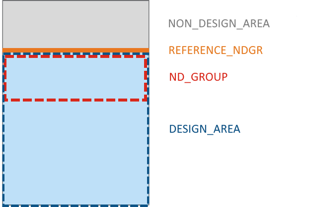
The following image shows how the different node groups are to be defined:

ND_GROUPis a subset ofDESIGN_AREA.REFERENCE_NDGRis a subset ofND_GROUPandNON_DESIGN_AREA
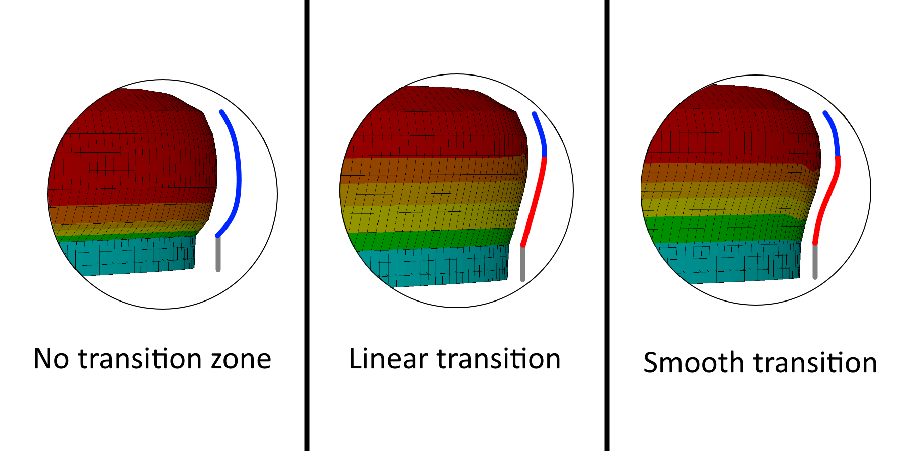
The different parameters for FUNCTION are visualized in the next image where
the grey profile represents the nondesign area, blue the design area and red is ND_GROUP:
