About the Hub Example | ||
| ||
About the Model
The optimization task is to lower the maximum von Mises stresses. The new design must show rotational symmetry by 120° with plane symmetrical segments. The assembly of the hub model is shown in the following figure:

The hub is modeled using 3D solid elements. The model is loaded with two moments in opposite direction and is fixed at the end of the shaft:
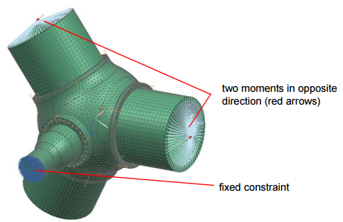
Inner and outer surface of the base body can be changed individually by the shape optimization. The connections modeled as nondesign nodes must be fixed:

Procedure Summary
| Model: | hub.ext |
| Design Area: | Node group design_nodes |
| Design Variable Constraint: | Apply boundary conditions for all nodes |
| Design variable Constraint: | Fixation of all displacements for the node group FIX |
| Design variable Constraint: | SURF_CYCLIC_PLANE-symmetry condition with start point (0,0,1), direction (1,0,0), and angle 120° in the global coordinate system |
| Mesh Smooth: | Mesh smoothing of all elements in the design area, while free surface nodes remain free |
| Objective: | Minimize the maximal von Mises stresses in the design area |
| Stop Condition | 10 iterations |