Adding a wire-from-edge feature

Select Shape Wire From Edge from the main menu bar to replace existing 3D shell or solid edges in the viewport with a wire feature.

See Also
What is feature-based modeling?
Adding a wire feature
The Sketch module

Context:

You add a wire from edge feature by picking one or more edges from the current part. Abaqus/CAE removes the faces along the selected edges, converts the part from a solid to a shell if necessary, and creates wires to replace the removed edges. A wire-from-edge feature is illustrated in the following figure:
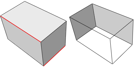
The image on the left shows the selected edges on the original solid part. The image on the right shows the resulting part. Each of the selected edges was associated with two faces; Abaqus/CAE removes those faces and converts the solid to a shell. The selected edges, and all the other edges that are no longer associated with faces, make up the new wire feature.

A wire-from-edge feature cannot be modified.

  1. From the main menu bar, select ShapeWireFrom Edge.

    Abaqus/CAE displays prompts in the prompt area to guide you through the procedure.

    Tip: You can also add a wire-from-edge feature using the tool, located with the wire tools in the Part module toolbox. For a diagram of the tools in the Part module toolbox, see Using the Part module toolbox.

  2. Select the edges to be replaced by wires.
  3. Click Done to create the wire feature.

    Abaqus/CAE displays a dialog box indicating that the faces and cells associated with the selected edges will be deleted.

  4. Click Yes to continue or No to cancel the procedure.

    If you choose Yes, Abaqus/CAE removes the faces associated with the selected edges and adds wires to replace all the removed feature edges.