Using the project edges method to partition faces | |||||
|
| ||||
Context:
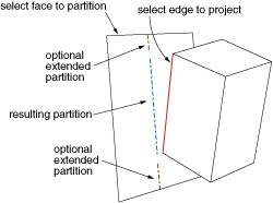
The figure below shows an example of partitioning selected faces using their
intersection or junction with the projection of one or more edges.

Abaqus/CAE
creates the partition by taking a perpendicular projection from the faces being
partitioned to the selected edges; nonplanar faces or faces joined at a sharp
edge such that there is a discontinuity in the perpendicular projection may
significantly change the shape of the projected edges. As shown in the figure,
you can create a partition that ends at the endpoints of the projected edges,
or you can extend the projected edges to reach the face boundaries. If you
extend the partition,
Abaqus/CAE
extends the free ends of the projected edges along their tangents to reach the
boundary edges of the faces being partitioned.
The faces and edges need not belong to the same part; for example, in the Assembly module you can partition faces belonging to one part instance using edges projected from a second part instance. The faces to be partitioned must be part of the active model representation. The edges can be part of the active representation or part of the reference representation for a midsurface model.
 tool, located with the partition face tools in the module
toolbox. For a diagram of the partition tools in the toolbox, see