About the Taguchi Robust Design Component | ||||
|
| |||
Upon execution in the Runtime Gateway,
Isight
automatically creates a Taguchi Results
aggregate parameter containing basic results (see About the Taguchi Robust Design Results Aggregate Parameter).
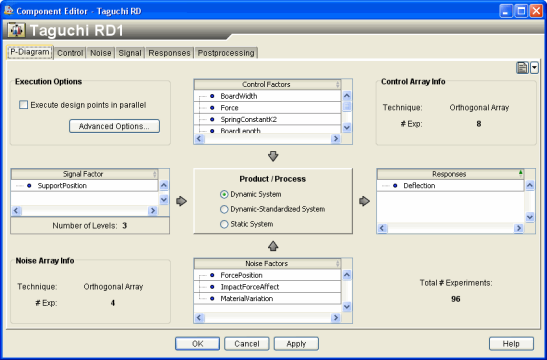
The following figure shows the Taguchi Robust Design Component Editor.
To start the Taguchi Robust Design Component
Editor, double-click the Taguchi Robust Design
icon  . When you have finished configuring the
Taguchi Robust Design Component Editor, click
OK to close the editor. For more information about
inserting components and accessing component editors, see Working with Components in the Isight User’s Guide.
. When you have finished configuring the
Taguchi Robust Design Component Editor, click
OK to close the editor. For more information about
inserting components and accessing component editors, see Working with Components in the Isight User’s Guide.
The Taguchi Robust Design Component Editor opens with the P-Diagram displayed. You use the P-Diagram tab to select execution options and the system type and to view a summary of the factors, responses, etc. that you selected while configuring the Taguchi Design Component. The P-Diagram tab shows the following information:
-
Execution Options. You can determine the options that you want the editor to take during execution.
-
Control Factors. The control factors represent design parameters under the designer’s control, which are fixed after design time (e.g., dimensions). The control array represents the combinations of values of each control factor to be executed as design points. The control array DOE technique and the number of experiment points appear in the Control Array Info area.
-
Noise Factors. The noise factors represent design parameters not under the designer’s control, varied to simulate/measure their effects on system variability (e.g., environment temperature). The noise array represents the combinations of values of each noise factor to be executed as system variation points. The noise array DOE technique and the number of experiment points appear in the Noise Array Info area.
-
Signal Factor and Number of Levels. The signal factor represents a parameter that you set when the product/process is being used (for example, thermostat setting, accelerator pedal position, etc.). A signal factor is defined only for dynamic systems. The number of levels for the signal factor is displayed when you select a signal factor. For information about levels, see Configuring the Factors.
-
Product/Process. You can choose Static System, Dynamic System, or Dynamic-Standardized System.
-
Responses. When the responses are selected and defined on the Responses tab, the information is added to the response block to complete the P-Diagram.
-
Total # Experiments. In most cases this number is equal to the number of control experiments multiplied by the number of noise experiments. For dynamic systems that include a signal factor, this number is equal to the number of control experiments multiplied by the number of noise experiments multiplied by the number of signal levels.