Overview of Internal Force | ||||
|
| |||
Parameter Name |
Formula |
|---|---|
INTERNAL_FORCE_ABS |
|
INTERNAL_FORCE_X, INTERNAL_FORCE_Y, INTERNAL_FORCE_Z |
|
INTERNAL_FORCE_X_ABS, INTERNAL_FORCE_Y_ABS, INTERNAL_FORCE_Z_ABS |
|
INTERNAL_MOMENT_ABS |
|
INTERNAL_MOMENT_X, INTERNAL_MOMENT_Y, INTERNAL_MOMENT_Z |
|
INTERNAL_MOMENT_X_ABS, INTERNAL_MOMENT_Y_ABS, INTERNAL_MOMENT_Z_ABS |
For the elements e attached to the nodes i.
Analysis Types: Static Linear or Nonlinear Analysis
where K might be linear or nonlinear.
For internal forces, the following table shows the allowed combinations between the strategy and
the items OBJ_FUNC and CONSTRAINT with C for controller and S
for sensitivity-based optimization.
TOPO |
SHAPE |
BEAD |
SIZING |
|
|---|---|---|---|---|
OBJ_FUNC |
S |
S |
S |
S |
CONSTRAINT |
S |
S |
S |
S |
The internal forces and the internal moments can be defined as a DRESP
(design response) in the sensitivity-based optimization approaches.
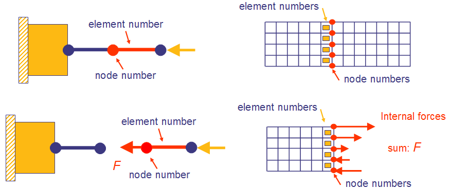
The internal forces as DRESPs are supported for Abaqus, ANSYS® and MSC Nastran®. The following figure shows the definition of internal forces through nodes and elements. On
the left the internal axial forces of a bar or beam is defined by using only one node and one
element. On the right side, the internal axial forces of a continuum element are defined by
summing up the forces in axial direction using a node and an element group.
 |
As previously shown, the internal forces are defined by nodes and elements. Meaning that the design response is defined in the following way:
DRESP
 ID_NAME = .....
 DEF_TYPE = SYSTEM
 TYPE = .....
 CS_DEF = .....
 GROUP_OPER = MAX  or  SUM
 ND_GROUP = .....or use the NODE-definition
 NODE = .....or use the ND_GROUP-definition
 EL_GROUP = .....or use the ELEM-definition
 ELEM = .....or use the ELEM_GROUP-definition
 LC_SET = .....
END_
Important:
|