Guide for Nonlinear Models | ||
| ||
Solver Settings
To obtain better convergence behavior, use the following settings when running an optimization with a nonlinear model:
*STEP, NLGEOM=YES, INC=10000, extrapolation=NO
** (INC=number of increments)
*STATIC
**(initial, step time, min, max)
0.1, 1.0, 1e-14, 1.0
In the following, Abaqus related remarks that should be taken into account when optimizing structures with nonlinear behavior are summarized.
| Topic: | Remark: |
|---|---|
| Time increment | By default, Abaqus
uses the automatic time incrementation based on the initial, step time, minimum, and maximum time
increments. In the case of a nonlinear analysis,
it is recommended to use a small minimum time increment as well as a higher number of increments
to run a stable analysis. The following default is the syntax for the
Abaqus
input file for the respective step.
                       *STEP, INC=100
                       ** (INC=increments)
                       *STATIC
                       ** (initial, step time, min, max)
                       1.0, 1.0, 1e-05, 1.0
Having a minimum time increment smaller than 1e-07 might further improve the
convergence but also strongly increases the computation time. More details can be found in the
Abaqus documentation. |
| Element type | Based on the utilized integration schemes the element types are split
into fully integrated elements like C3D8 or C3D4 and reduced integrated elements like C3D8R. In the
case of reduced integration elements in the model, activate the enhanced hourglass technique. The
following is the syntax for the Abaqus
input file:
|
| Solver instabilities | If the optimization fails because of Abaqus
convergence issues, further details can be investigated in the *.msg or *.dat files generated
by Abaqus in the critical step. The following are the
most expected warnings or errors:
|
| Stabilization and contacts | In nonlinear static problems, instabilities like buckling or material
softening might occur. If these instabilities are localized, there a local transfer of strain energy
occurs from one part to another and global solution methods might not work. Here, automatic
(artificial) damping stabilization might help. The damping might help to get the model to converge but
at a loss of convergence speed and accuracy. Therefore, the damping factor is best to be chosen
as small as possible. The ratio of stabilization dissipation energy (ALLSD) to internal energy
(ALLIE) of the whole model should not be bigger than 5%. By default, the value is
FACTOR=2e-4. The following is the syntax for the
Abaqus
input file for the respective step:
It might also help to use
for contacts to relax the liner penalty stiffness. The default is 1.0.
Note:
A “good” value for the damping factor can be different from one model to another. In cases with
contact modeling, rigid body motion might occur while the contact is not fully established.
By using *CONTACT CONTROL, STABILIZE, artificial damping is
introduced to increase stabilization. The damping coefficient is calculated automatically by default
if no value is assigned.
Note:
When using step and contact stabilization simultaneously, a type of
"over-damping" occurs and the result becomes physically unrealistic. Therefore, a combination
of both commands is not recommended.
|
| Solving convergence problems | For some convergence issues, it is not required to change the physics
of the models at all. The following warnings/errors can be found in the *.msg file.
|
| Other step settings | Quite often the error message is not specific or might have different
causes. Therefore, a few additional commands are mentioned in the following
that might help to get the model to converge.
|
Error Messages in .msg-files
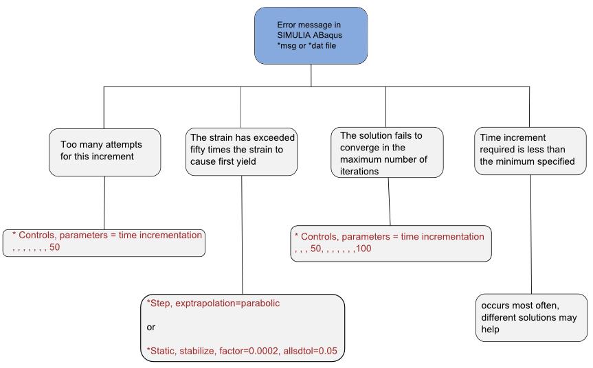 |
The above error messages appear most often in the .msg file during a failed optimization. The corresponding command might solve the problem. The error “time increment required is less the minimum specified” occurs with different problems and cannot be solved with a single command. It helps to analyze the model with respect to tie contact, plasticity, element size, and other instabilities.