Typical Tasks for Static Analysis | ||
| ||
Minimizing Mass with Stiffness Restrictions
If the structure with the minimal volume (mass) subject to displacement constraints (corresponding to a restriction on the mechanical stiffness) is sought, the optimization task is formulated as follows:
where Vol is the relative material volume of an element in the design area, is the nodal displacement and is the restriction for the nodal displacement of the node j.
A model for the minimization of the relative material volume under the displacement of the loaded nodes is presented in the example below.
The following figures show different load case with its constraints and the corresponding formula. The amplitude of the distortion is defined by two variables: u1 and u2 give the displacement at the two pints where the load is applied. The indices x and z are directions in local or global coordinate systems.
Bending stiffness 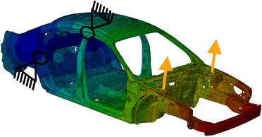 target bending |
Torsional stiffness 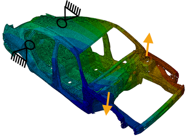 target torsional |
Axial stiffness 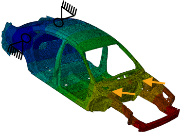 target axial |
Necessary Definitions
Two design responses are needed:
- The first design response is the design response representing the relative material volume of the design area. This design response is the objective function that is to be minimized.
- The second design response is the displacement of the loaded node. The absolute displacement is used in this case. Alternatively, the displacement in the direction of the load (in the example it is z- or x-direction of a local coordinate system) can be used. The restriction to one direction reduces the number of load case generated by the optimization system because using absolute displacement leads to the need of 3 additional load case in order to calculate the sensitivities while the displacement in z-direction only requires one additional pseudo-load case for the calculation of the sensitivities. The constraint is then defined as an inequality constraint with an absolute value for the displacement value.
Result and Convergence
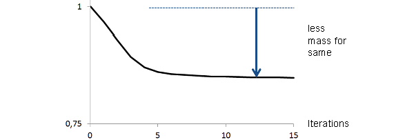
The objective function (minimize mass - mass normalized) is pictured in the following figure.
 |
The constraints (stiffness restrictions) are shown in the next figure.
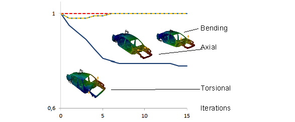 |
In the figure above, you can see the gradient of the normalized mass about 15 Iterations. In this example, the reduction amounts about 15%. Also, the gradients of the normalized three stiffness constraints for the three load case (bending, axial and torsional) are illustrated. What you can see is, that they are fulfilled.