Coupled Acoustic-Structural Optimization of Car Cabin | ||
| ||
Description of the Model
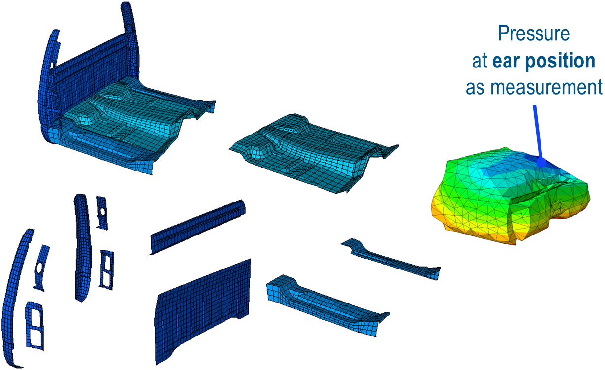
The model is of the floor and back panels of a car as shown in the image below. A frequency analysis, followed by a steady state dynamic analysis is being performed.
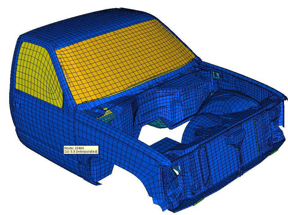
The cabin is modeled with shell elements and the air inside the cabin is modeled with acoustic elements. Since this is an internal acoustic analysis,
we also couple the cabin structure and the air inside it using Tie constraints. Thus this is a Fully Coupled Structural-Acoustic Analysis.
A node set near the ear position in the cabin is defined to measure the acoustic pressure.
The floor and back panel regions of the cabin to be optimized are shown below in the figure, along with the region where acoustic pressure is measured.
 |
The complete FE model of the car with acoustic elements. The acoustic elements model the air inside the cabin are colored yellow:
 |
Description of the Optimization Problem
The optimization problem is to minimize the sound pressure while keeping the volume of the design area the same as before. Also thickness bounds have been specified, along with clustering of elements. This is done to keep the results in a mechanically sensible range, and to ensure ease of manufacturing. The parameter file is shown below:
DRESP
  ID_NAME  = TOSCA_DRESP_1_FREQUENCY_RESPONSE_TERM_1
  DEF_TYPE = SYSTEM
  ND_GROUP = AIR-1_EAR_POSITION
  TYPE     = FS_PRESSURE
  LC_SET   = ALL,1,All
END_

DRESP
  ID_NAME    = TOSCA_DRESP_2_VOLUME_CONSTRAINT_1
  DEF_TYPE   = SYSTEM
  EL_GROUP   = DV_FLOOR_AND_BACK_PANELS
  TYPE       = VOLUME
  UPDATE     = EVER
  GROUP_OPER = Sum
END_

OBJ_FUNC
  ID_NAME = OBJ_FUNC_1_OBJ_FUNC_ITEM_1
  TARGET  = MIN
  DRESP   = TOSCA_DRESP_1_FREQUENCY_RESPONSE_TERM_1,
END_

CONSTRAINT
  ID_NAME   = CONSTRAINT_1_VOLUME_CONSTRAINT_1
  DRESP     = TOSCA_DRESP_2_VOLUME_CONSTRAINT_1
  MAGNITUDE = REL
  LE_VALUE  = 1.
END_

....

DVCON_SIZING
  ID_NAME     = BOUNDS_ID
  EL_GROUP    = DV_FLOOR_AND_BACK_PANELS
  CHECK_TYPE  = THICKNESS_BOUNDS
  MAGNITUDE   = REL
  LOWER_BOUND = 0.5
  UPPER_BOUND = 2.0
END_

....

The damping must be consistently specified in the Abaqus input file as well

OPT_PARAM
  ID_NAME            = MY_PARAMETERS
  OPTIMIZE           = OPTIMIZE_1
  THICKNESS_UPDATE   = CONSERVATIVE
  THICKNESS_MOVE     = 0.05
  DAMP_VISCOUS_STIFF = 4.e-5
END_

EXIT
Results
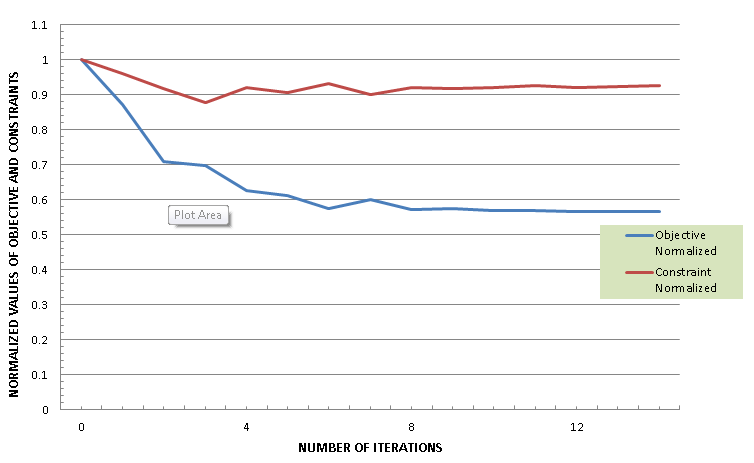
The figure below shows the normalized values of the objective function and the constraints over the optimization process:
 |
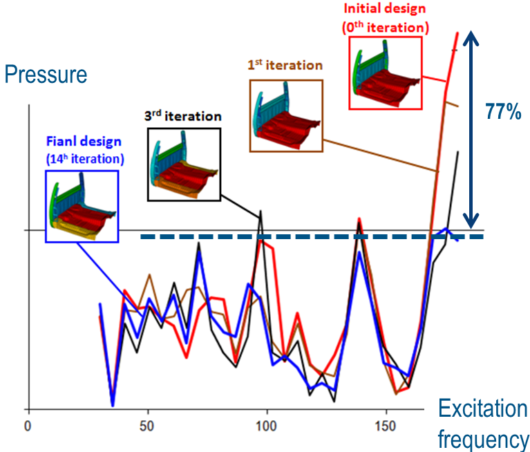
The following figure shows the changes in the design, and the improvement of acoustic and frequency responses with the progress of optimization:
 |
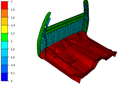
The next figure represents the original design:
| The thickness distribution of the original floor and back panel assembly |
 |
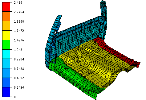
Shown below is the optimized design.
Although the solution has a higher maximum thickness, the total volume is lesser than the original design also with decrease in acoustic pressure at the required positions in the cabin.
| The thickness distribution of the optimized floor and back panel assembly |
 |