Sizing Optimization for Circular Beams | ||
| ||
Supported Finite Element Features for Circular Beams
The circular beam type based on the Timoshenko beam element formulation is supported for optimization. The corresponding element type definition is summarized in the following table for different solvers:
| Solver | Element type definition |
|---|---|
| Abaqus | *ELEMENT, TYPE=B31 |
| ANSYS® | ET, 1, 188 |
| Circular beam |
|---|
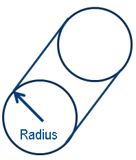 |
As shown in the above picture, the radii of circular beams are supported as design variables. Thus, the following cross section property definition is supported for sizing optimization:
| Solver | Cross section definition |
|---|---|
| Abaqus | *BEAM SECTION, SECTION = CIRC |
| ANSYS® | SECTYPE,1,BEAM,CSOLID SECDATA,25., |
The radii of the circular beam sections can be optimized simultaneously with the elemental shell thicknesses. Outside of the design area, any type of elements can be applied. In the design area, linear and nonlinear material behavior is allowed (that is, plasticity or other geometrical nonlinearities). Contact and constant temperature loadings are supported in context of sizing optimization for circular beams. In addition, both linear static and linear modal type analysis are supported.
The main features and the corresponding comments are summarized in the following table:
| Features | Comment |
|---|---|
| Simultaneously usage of circular beams and shells | Supported |
| Contact | Supported, also for design elements |
| Constitutive nonlinear modeling outside the design area | Supported |
| Constitutive nonlinear materials in design area | Supported |
| Temperature loading | Design independent temperature loading is supported |
| Geometrical nonlinearities | Supported |
| Linear static analysis | Supported |
| Linear modal analysis | Supported |
| Steady-state dynamics | Supported |
Optimization Formulation Options for Circular Beams
All the existing design responses except stresses are supported for sizing optimization with circular beams and can be used for constraints and objective function definitions. All the symmetry constraints available in the sizing module can be applied simultaneously with variable bounds and clustering on design radii. The number of load cases is not limited. DRESPs from static, modal (eigenfrequency) and frequency response (also vibroacoustic) analyses are supported. All the mentioned features are summarized in the following table:
| Feature | Comment |
|---|---|
| DRESPs for static load cases | Supported; for example, Stiffness, Displacements, Forces … |
| Multiple load cases | Supported, arbitrary number |
| DRESPs for modal eigenfrequency analysis | Supported, eigenfrequencies |
| DRESPs for frequency response analysis | Supported, also vibroacoustics |
| Mass | Supported |
| COG and Inertia | Supported |
| Symmetry constraints | Supported, various constraints |
| Variable bounds and clustering | Supported |
| DRESPs with stresses | Not supported |
Limitations
The limitations of sizing optimization for circular beams are as follows:
- Only Abaqus and ANSYS® solvers are supported.
- Only circular beam section type is supported with radius as design variable:
Solver Cross section definition Abaqus *BEAM SECTION, SECTION = CIRCANSYS® SECTYPE,1,BEAM,CSOLID SECDATA,25., -
Only the Timoshenko type beam element is supported:
Solver Element type definition Abaqus *ELEMENT, TYPE=B31ANSYS® ET, 1, 188 - Design responses with stresses are not supported.
Introduction Example for Abaqus
Within this example, the definition of a sizing optimization problem for circular beams is demonstrated. We consider the following model with the illustrated boundary conditions.
| Mechanical model |
|---|
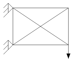 |
The model corresponds to a cantilever beam that consists of 8 elements. It is supported on the left nodes and loaded at the right bottom node.
The corresponding Abaqus input file is given below:
*Heading
** Job name: example Model name: Model-1
** Generated by: Abaqus/CAE 6.14-2
*Preprint, echo=NO, model=NO, history=NO, contact=NO
** PART INSTANCE: Part-1-1
*Node
1,          -1.,  0.600000024,           0.
2,           0., -0.100000001,           0.
3,           1., -0.800000012,           0.
4,          -1., -0.800000012,           0.
5,           1.,  0.600000024,           0.
*Element, type=B31
1, 1, 2
2, 2, 3
3, 4, 3
4, 4, 2
5, 2, 5
6, 5, 1
7, 1, 4
8, 3, 5
*Nset, nset=Part-1-1_Set-1, generate
1,  5,  1
*Elset, elset=Part-1-1_Set-1, generate
1,  8,  1
*Nset, nset=Part-1-1_Set-4, generate
1,  5,  1
*Elset, elset=Part-1-1_Set-4, generate
1,  8,  1
*Nset, nset=Part-1-1_Set-5, generate
1,  5,  1
*Elset, elset=Part-1-1_Set-5, generate
1,  8,  1
*Orientation, name=Part-1-1-Ori-1
1., 0., 0., 0., 1., 0.
1, 0.
** Section: Section-1  Profile: Profile-1
*Beam Section, elset=Part-1-1_Set-1, material=steel,
temperature=GRADIENTS, section=CIRC
0.1
0.,0.,1.
*System
*Nset, nset=Set-1
3,
*Nset, nset=Set-2
1, 4
*Nset, nset=Set-3
3, 5
*Nset, nset=_PickedSet7
3,
*Nset, nset=_PickedSet8
3,
** MATERIALS
*Material, name=steel
*Density
7850.,
*Elastic
2e+11, 0.33
** STEP: Step-1
*Step, name=Step-1, nlgeom=NO
*Static
1., 1., 1e-05, 1.
** BOUNDARY CONDITIONS
** Name: BC-1 Type: Symmetry/Antisymmetry/Encastre
*Boundary
Set-2, ENCASTRE
** LOADS
** Name: Load-1   Type: Concentrated force
*Cload
_PickedSet8, 2, 1e+06
** OUTPUT REQUESTS
*Restart, write, frequency=0
** FIELD OUTPUT: F-Output-1
*Output, field, variable=PRESELECT
** HISTORY OUTPUT: H-Output-1
*Output, history, variable=PRESELECT
*End Step
The corresponding Tosca Structure parameter file is given in the following.
For the present optimization, we maximize the stiffness by minimizing the deflection and at the same time we keep the original mass of the structure. The original mass is enforced using a relative constraint of exactly one. The initial radii are equal to 0.1. The upper and lower bounds on the radii are set to 0.12 and 0.01.
FEM_INPUT
 ID_NAME = example
 FILE    = example.inp
END_

DRESP
 ID_NAME    = Disp
 LIST       = NO_LIST
 DEF_TYPE   = SYSTEM
 TYPE       = DISP_ABS
 ND_GROUP   = _PickedSet7
 GROUP_OPER = MAX
 LC_SET     = ALL, 1, ALL, MAX
END_

DRESP
 ID_NAME    = Mass
 LIST       = NO_LIST
 DEF_TYPE   = SYSTEM
 TYPE       = WEIGHT
 EL_GROUP   = ALL_ELEMENTS
 GROUP_OPER = SUM
END_

DV_SIZING
 ID_NAME  = Task-1_DESIGN_AREA_
 EL_GROUP = ALL_ELEMENTS
END_

DVCON_SIZING
 ID_NAME        = MY_DVCON_SIZING
 CHECK_TYPE     = THICKNESS_BOUNDS
 EL_GROUP       = ALL_ELEMENTS
 LOWER_BOUND    = 0.01
 UPPER_BOUND    = 0.12
 MAGNITUDE      = ABS
END_

OBJ_FUNC
 ID_NAME = Minimize_Disp
 DRESP   = Disp, 1.
 TARGET  = MIN
END_

CONSTRAINT
 ID_NAME   = Weight_100
 DRESP     = Mass
 MAGNITUDE = REL
 LE_VALUE  = 1
END_

OPTIMIZE
 ID_NAME    = Task-1
 DV         = Task-1_DESIGN_AREA_
 OBJ_FUNC   = Minimize_Disp
 CONSTRAINT = Weight_100
 STRATEGY   = SIZING_SENSITIVITY
 DVCON      = MY_DVCON_SIZING
END_

EXIT
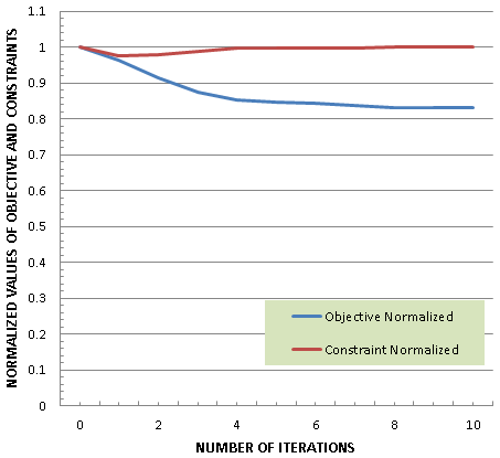
The optimization results are shown in the following figures. The displacement value of the right bottom node is decreased, and the structural volume corresponds to its initial value. The upper and lower bounds of design variables are not violated.
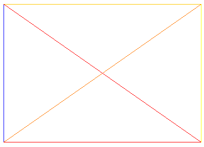
| Optimization history | Optimized radii | Thickness |
|---|---|---|
 |
 |
 |
Introduction Example for ANSYS®
Within this example, the definition of a sizing optimization problem for circular beams is demonstrated. In particular, there is only one beam with one fixed node (left on the picture) and fixed moment of inertia. In addition, there is a force applied on the other node along the Z direction.
| Mechanical model |
|---|
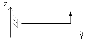 |
The corresponding ANSYS® input file is given below:
! Model name: thick_beam.cdb

/PREP7
/NOPR
LOCAL,R5.0,LOC,11,0,-45.,-17.8483,11.7365
LOCAL,R5.0,ANG,11,0,0.,-90.,0.
LOCAL,R5.0,PRM,11,0,1.,1.
CSYS,11
N,230857,0.,9.98750019,100.
N,230858,0.,9.98649979,0.
CSYS,0
MP,EX,1,10.
MP,PRXY,1,0.3
MP,DENS,1,7.85E-9
ET,1,188
SECNUM,1
SECTYPE,1,BEAM,CSOLID,Beam Section,0
SECOFFSET,SHRC,,,,,,
SECDATA,25.,,,,,,,,,
EBLOCK,19,SOLID
(19i8)
1  1  0  1  0  0  0  0  2  0 1274067  230857  230858
-1
D,230857,ALL,0.,0.
/SOLU
!
! L O A D - S T E P S
!Anonymous Ansys Step 1
!
TIME,1.
!
F,230858,FZ,50.,0.
solve
FINISH
The corresponding Tosca Structure parameter file is given below. For the present optimization, we maximize the stiffness by minimizing the deflection. The initial radius is equal to 25.0 units.
FEM_INPUT
 ID_NAME = MY_INPUT_FILES
 FILE    = thick_beam.cdb, ansys
END_

DRESP
 ID_NAME   = DRESP_DISP
 DEF_TYPE  = SYSTEM
 TYPE      = DISP_ABS
 NODE      = 230858
 CS_REF    = CS_0
END_

DRESP
 ID_NAME   = DRESP_VOL
 DEF_TYPE  = SYSTEM
 TYPE      = WEIGHT
 EL_GROUP  = ALL_ELEMENTS
END_

OBJ_FUNC
 ID_NAME   = MY_OBJ_FUNC
 TARGET    = MIN
 DRESP     = DRESP_VOL, ,
END_

CONSTRAINT
 ID_NAME   = CONSTRAINT_DISP
 MAGNITUDE = ABS
 DRESP     = DRESP_DISP
 LE_VALUE  = 0.9
END_

DV_SIZING
 ID_NAME  = DESIGN_AREA
 EL_GROUP = ALL_ELEMENTS
END_

OPTIMIZE
 ID_NAME    = OPTIMIZE_1_SIZING_OPTIMIZATION
 DV         = DESIGN_AREA
 OBJ_FUNC   = MY_OBJ_FUNC
 CONSTRAINT = CONSTRAINT_DISP
 STRATEGY   = SIZING
END_

STOP
 ID_NAME  = GLOBAL_STOP_CONDITION_1
 ITER_MAX = 50
END_
Result: The output of the optimization shows that the radius of the beam is now thicker with 5 more units (R = 30).
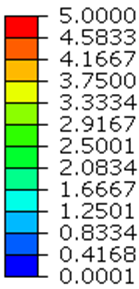
Optimization Example: Combined Optimization of Outer Shell Elemental Thicknesses and Elemental radii of Inner Ground Structure
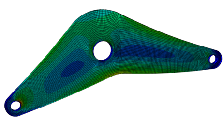
We consider the following model with the illustrated boundary conditions, pictured initial deformation, and the corresponding initial stress.
| Mechanical model | Deformation | Stress |
|---|---|---|
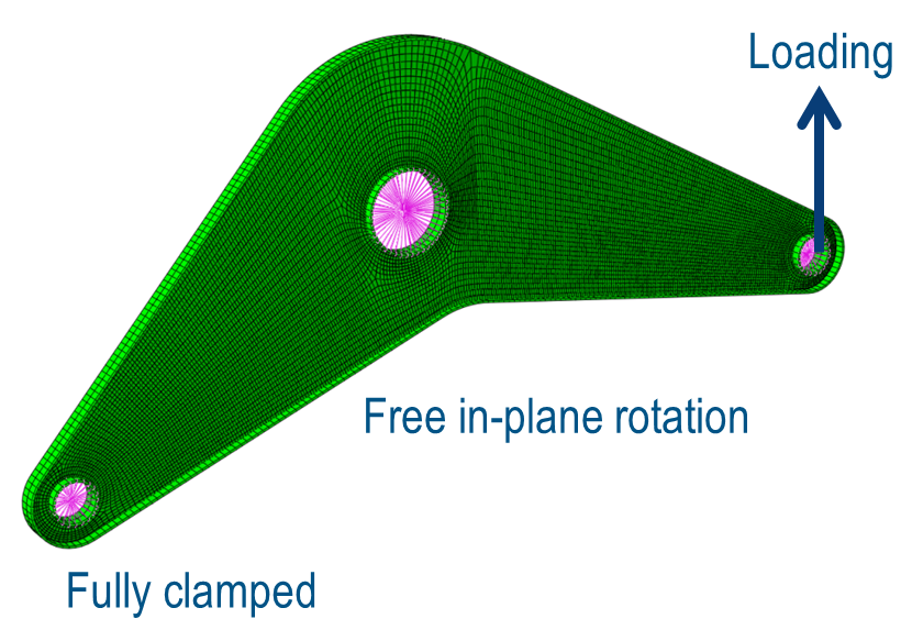 |
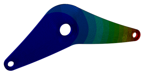 |
 |
The structural mass is to be minimized, while keeping the displacement at loading point less than 0.6mm. The inner structure is consisting of either shell thicknesses or lattice build of circular beams. The design variables either the inner shell thicknesses or the radii of the lattice simultaneously with the elemental thicknesses of the other shell reinforcements.
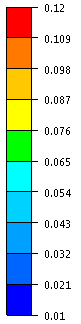
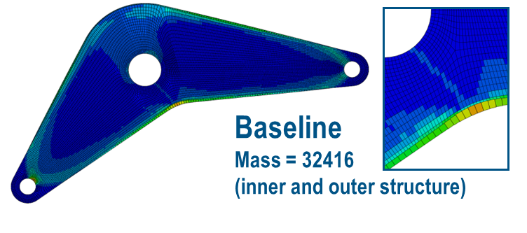
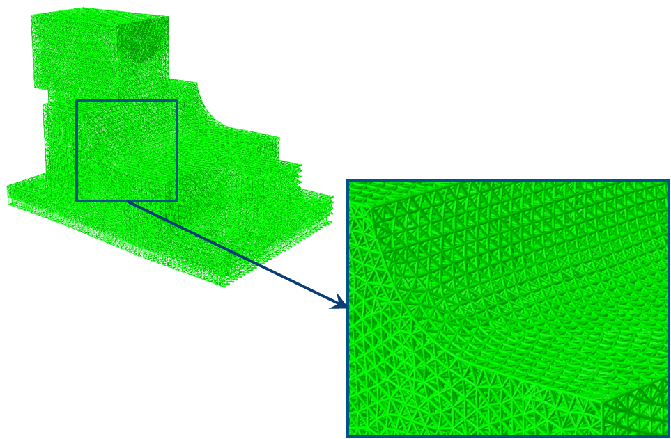
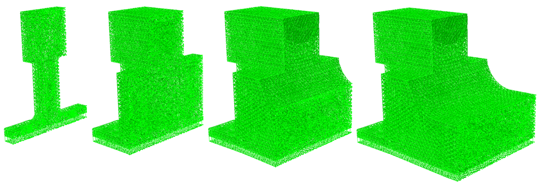
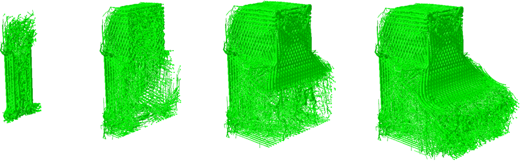
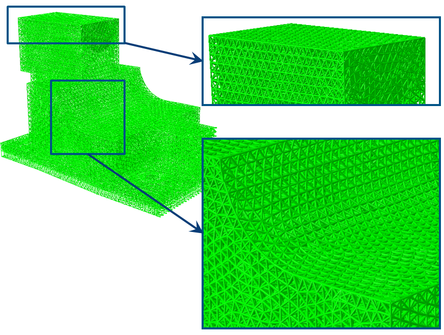
The optimization results are shown in the following figure:
| Thickness | Free continuous shell thickness | Triangular fine lattice |
|---|---|---|
 |
 |
 |
| Thickness | Triangular medium lattice | Triangular coarser lattice |
|---|---|---|
|
|
 |
 |
Optimization Example: Lattice Optimization of Door Stop.
We consider the following model.
 |
Optimization Objectives:
- Maximize stiffness
- Keep the original structural mass
- Displacement for interface constraints
Radius of circular beam element:
- Initial: 0.18
- Lower bound: 0.00001 (approximates void)
- Upper bound: 0.7 (289%)
The following figure represents the section cuts for the original structure having uniform radius sections for the entire structure:
 |
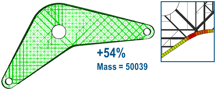
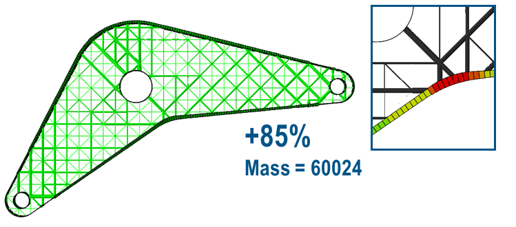
The next figure shows the radius distribution of the section cuts for the optimized structure:
 |
Some enlarged details of the initial and the optimized structures are pictured in the following figure:
| Initial radii | Optimized radii |
|---|---|
 |
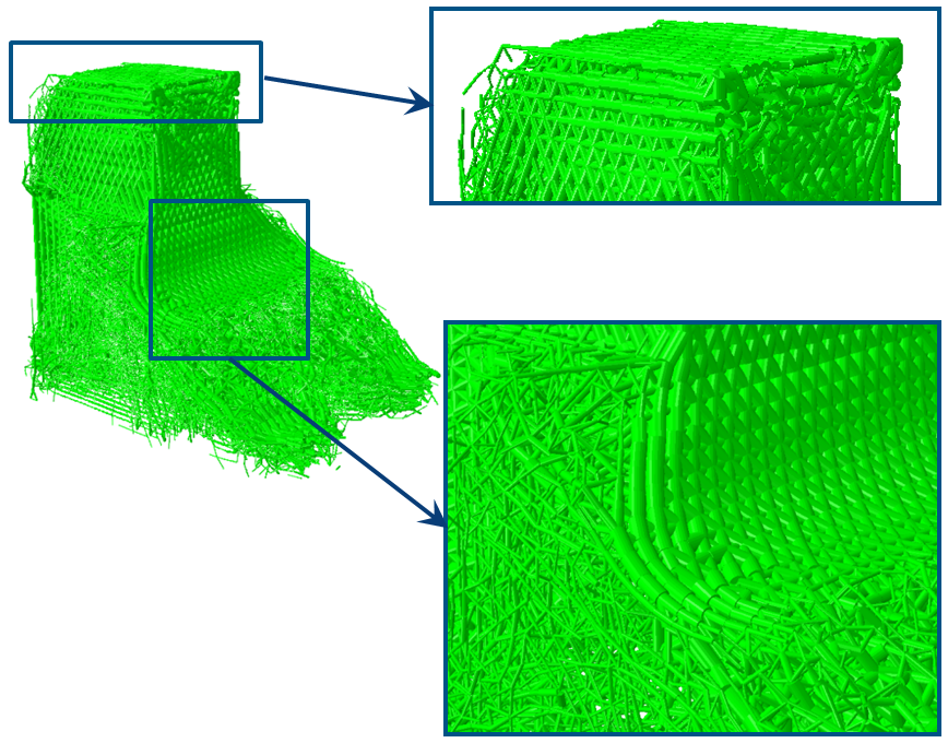 |
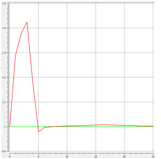
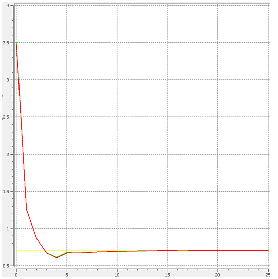
The following figures show the optimization iteration history for the design responses being the stiffness energy measure for the objective and mass and displacement as constraints:
| Stiffness energy measure | Mass (normalized) | Displacement interface constraints |
|---|---|---|
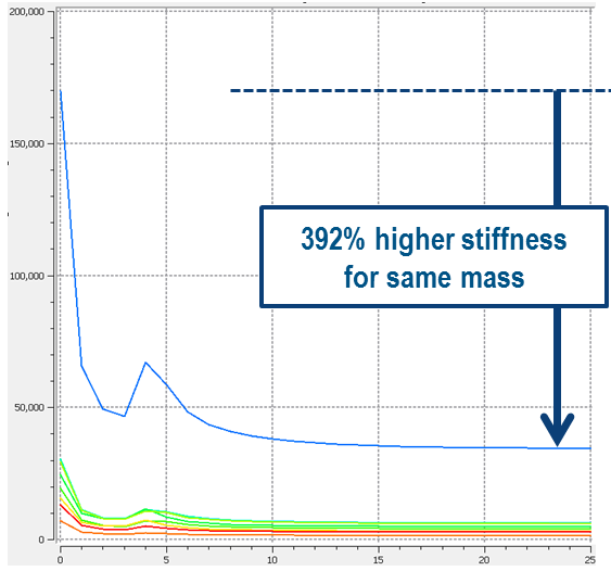 |
 |
 |