Settings for controller-based shape optimization | |||||||
|
| ||||||
The user can set several optimization parameters using the OPT_PARAM
command and thereby influence the controller response.
- In Tosca Structure.gui, the settings are defined in OPT_PARAM command.
Each OPT_PARAM command has a unique name (ID_NAME
parameter) and references a previously defined optimization job (OPTIMIZE
command). The specified parameters only relate to the given optimization
task. A typical OPT_PARAM command appears as follows:
OPT_PARAMID_NAME = param_for_shape_optimization OPTIMIZE = shape_optimization ...END_
Six parameters can be set by the user for shape optimization:
- Scaling of the allowed amount of displacement
- Treatment of the midside nodes during the optimization
- Curvature-based modification of the optimization movement vector
- Filtering of the optimization displacements
- Updating of the normal vectors (optimization displacement vector)
- Control of the increments according to the allowed displacements
OPT_PARAM command is also used in topology optimization.
However, the optimization parameters that can be set depend on the type
of optimization. The only parameters that can be set here are those
allowed for shape optimization.Scale of Displacement (SCALE)
The controller provides an automatic increment control of the optimization
displacements. An initial increment is first determined based on the
mesh of the FE start model. The size of the increment is then automatically
adjusted in every design cycle. Usually, the user does not need to modify
the increment control manually. The user can increase or decrease the
increment using a scaling factor (SCALE parameter):
 ...
 SCALE = <REAL_value>
 ...
The default setting is SCALE=1.0, hence, the optimization
displacements are applied in increments determined by the controller.
If the selected scaling factor has a value greater than one, the increment
size determined by the controller will increase correspondingly. therefore,
the optimization is accelerated. On the other hand, if the selected scaling
factor has a value less than one, the increment size determined by the
controller will decrease accordingly. Thus, the optimization is slowed
down.
Example: With SCALE=2.0 the increment size as determined
by the controller is doubled. With SCALE=0.8 the increment
size of the controller is reduced to 80% of the initial increment size.
The scaling factor can be split in a factor for growth and a factor for shrinkage:
 ...
 SCALE = <grow_value>, <shrink_value>
 ...
Important:
|
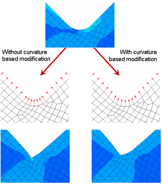
Curvature-Based Modification of Optimization Displacements
The node-based optimization movement vector is modified in areas of high
curvature to prevent a collapse of the mesh for large volume changes
(CURV_SMOOTH). A bigger radius causes a bigger curvature-based
modification of the optimization movement vector. (Default=5.0
* element edge lengths; OFF=0.0)
...
 CURV_SMOOTH = 5.0
 ...
 |
Filter Function for the Optimization Displacements (FILTER)
To smooth local peaks of the nodal reference stresses, the item FILTER
can be specified to activate a filter function:
...
 FILTER = <radius>, <sigma>, <exponent>
 ...
The filter is given by:
is the filter value for node j. The main filter function (B) decreases with the distance (d) between node i and j. The maximal radius () defines the maximum distance for the nodes i to influence the filter value. The curvature dependency () defines a weight function to reduce the radius at higher local surface curvature () approximated by the vector product of the node normal () to the neighboring nodes ().
SIGMA () and EXPONENT
(p) are optional with the default values (0.2 and 1., respectively).
The smaller the SIGMA, the larger is the influence of
the surface curvature. To avoid this effect, use a large SIGMA
value (for example, 10,000).
The exponent value defines the weight function which controls the influence depending on the distance from the node.
To smooth local peaks of the nodal reference stresses, use the DRESP
OPER=FILTER which gives the user the possibility to define filters
that correspond to single design responses. Example:
DRESP
 ID_NAME  = DRESP_MISES_FILTERED
 DEF_TYPE = OPER
 VAR_OPER = FILTER
 VAR_A    = DRESP_MAX_MISES
 RADIUS   = 30.0
 EXPONENT = 1.0
 SIGMA    = 1.0
END_
The parameters RADIUS, EXPONENT and SIGMA
have the same meaning as in the filtering of nodal displacements.
Important:
Large values of RADIUS might increase CPU-time. |
Control of the Amount of Optimization Displacement (DISP)
Based on the current FE mesh, an allowed amount of displacement is determined for every design node. This displacement variable limits the amount of the optimization displacement. Thus, optimization displacements that are greater than the allowed displacements are scaled back automatically to the allowed value node by node. This is intended for avoiding the collapse of a neighboring element when having a large optimization displacement of one node.
The controller provides automatic increment control of the optimization displacements. The increment size is dependent on the allowed displacements of the design nodes. A decrease of the allowed displacements (a decrease in the quality of the FE mesh) automatically leads to a decrease in the increment size of the controller. The increment size of the controller is automatically adjusted in every design cycle.
The DISP parameter enables the user to specify which
allowed displacement is to be used in the increment control:
...
 DISP  =  [ MINIMUM | AVERAGE ]
 ...
DISP=AVERAGE is the mean value of the allowed amount
of displacement for the design nodes used in the increment control; DISP=MINIMUM
(default) is the smallest value used. The setting DISP=AVERAGE
delivers a larger increment size and consequently a faster approximation
to the optimum. However, this opens for the possibility that nodes for
which only small displacements are allowed move too little causing ‘undesirable
corners’ in the design area.