The Optimization Task | ||
| ||
The following describes the general procedure for the definition of an optimization task. These procedures are supported by the command tree in Tosca Structure.pre screen of Tosca Structure.gui (GUI).
Analysis Model
- Question: Which file(s) contains the FE-model for the optimization?
- Procedure: Link file(s) to optimization task.
In GUI: Select and choose your model file.
Design Area
- Question: Which surface area of the FE model should be selected for shape modifications?
- Procedure: Assign node group with surface nodes to design area.
In GUI: Choose or define the node group with the surface nodes of the selected design area GROUP_DEF Command and define the design variables DV_SHAPE.
- Question: Which area of the model should be selected for smoothing of the FE mesh?
- Procedure: Assign element group to
MESH_SMOOTH area.
In GUI: Choose or define the element group defining the mesh smoothing area (GROUP_DEF) and define the mesh smoothing (MESH_SMOOTH).
- Question: Are there nodes in the design area or in the mesh smoothing area that are subject to certain restrictions? How can these restrictions be described?
- Procedure: Define design variable
constraints for node group.
In GUI: Choose or define node groups with common restrictions (GROUP_DEF). Define the restrictions using LINK_SHAPE and DVCON_SHAPE.
Objective function
- Question: Which terms describe the values to be optimized? Should these values be minimized or maximized or otherwise combined?
- Procedure:
Choose terms for optimization (design responses) and target.
In GUI: Define the design response (DRESP) and assign it to the objective function (OBJ_FUNC).
Constraint
- Question: Which design response describes the constraint? Which value should the constraint have?
- Procedure: Choose term for
constraint and set target value or upper/lower boundary.
In GUI: Define the design response (DRESP) and assign it to the constraint (CONSTRAINT).
Optimization Task
- Question: Are all command definitions listed above complete and ready for the optimization job?
- Procedure: If necessary
complete any additional required definitions and prepare the optimization
job.
In GUI: Reference all definitions above in OPTIMIZE.
Stop Condition
- Question: Should the optimization stop after a number of iterations (or certain other conditions)?
- Procedure: Define a stop condition.
In GUI: Select .
Check Run
- Question: Would prior testing of the restriction definitions be useful?
- Procedure: Apply test displacements.
In GUI: Select .
Completion
- Question: Has all the required data been specified?
- Procedure:
If yes, finish the definition of the optimization problem and save your
definition.
In GUI: Save as <jobname>.par.
The essential commands required for the optimization model in shape optimization are described in the following. The order of their appearance corresponds to the order of the above listed procedures.
The definitions for the optimization job are assembled in a parameter file. The exact syntax of the commands can be looked up in commands manual. The following figure gives an overview of a standard optimization task and the relation between the several commands. Only commands which are referenced in the OPTIMIZE command will be included in the optimization.
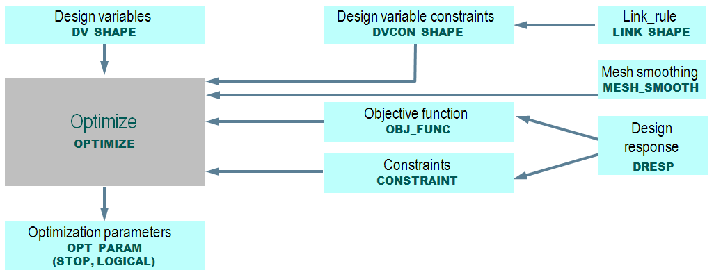 |