| Applicable for |
Controller (SHAPE_CONTROLLER) |
Sensitivity (SHAPE_SENSITIVITY) |
| CHECK_SLIDE |
OK |
- |
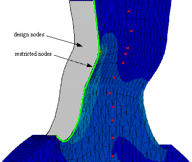
Element surfaces can be defined as slide surfaces in order to force
the design nodes onto this contour (CHECK_SLIDE). This
option offers more flexibility than restricting the direction of displacement.
The limiting surfaces are formed by shell structures. Those surfaces
can be generated automatically with a link shape command.
A main node group is required describing sufficiently the contour
of the surface. The following command defines a surface of revolution
with rotation axis Z in the global coordinate system:
LINK_SHAPE
 ID_NAME     = surface
 MAIN     = NDGR, slide_main_ndgr
 CLIENT     = SURF_TURN
 CLIENT_DIR = 0, 0, 1
 TOL        = 0.1, 0.1, 0.1
 CS         = CS_0
END_
This slide surface is connected to a node group by a DVCON_SHAPE command:
DVCON_SHAPE
 ID_NAME     = slide_restriction
 CHECK_SLIDE = surface
 ND_GROUP    = restricted_nodes
END_
Alternatively, the limiting surfaces are generated in the FE preprocessor
and loaded through the interface (FEM_INPUT command, ADD_FILE
parameter) in the optimization preprocessor. With a LINK_SHAPE
command
LINK_SHAPE
 ID_NAME  = surface
 MAIN     = NDGR, slide_ndgr
 CLIENT   = FREE_FORM
 TOL      = 0.1, 0.1, 0.1
 CS       = CS_0
END_
Here, the node group slide_ndgr is used to generate the
surface on which the design nodes will be restricted. The
CLIENT = FREE_FORM allows for freeform surfaces.