Penetration Checks | ||||||
|
| |||||
| Applicable for | Controller (SHAPE_CONTROLLER) | Sensitivity (SHAPE_SENSITIVITY) |
|---|---|---|
| CHECK_SOLID | OK | OK |
| CHECK_ELGR | OK | OK |
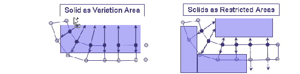
Displacement Check against Solids (CHECK_SOLID)
It is possible to define geometric primitives (solids) as a restriction
of the node displacements. Geometric primitives are defined using the
SOLID parameter. The SOLID command
allows the definition of:
- circles
- circle segments
- ring segments and rectangles in two-dimensional models and cylinders
- cylinder segments
- tubes
- cubes and cube segments in three-dimensional models
The parameter:
CHECK_SOLID = solid_name
specifies a solid whose borders might not be penetrated.
The following figure shows a displacement check against a solid:
 |
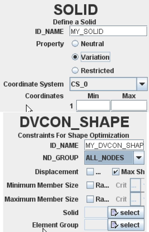
Defining a Solid
- To define a solid in Tosca Structure.gui, choose Command
SOLID.
Important:
|
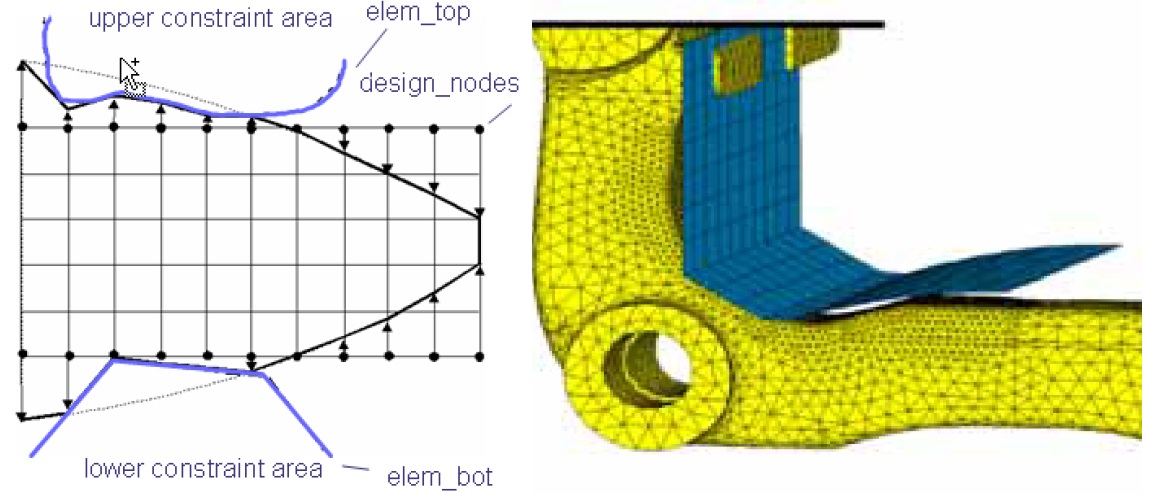
Penetration Check (CHECK_ELGR, PENETRATION_CHECK)
Element surfaces and lines as well as solid elements can be defined as limiting surfaces, lines,
or solids to check node displacements against any contour. This option offers more
flexibility than the check for the absolute amount of displacement or the check against
geometric primitives. The limiting surfaces are formed by beam structures in 2D models and
by shell structures or solid structures in 3D models. The limiting surfaces are generated in
the FE preprocessor and loaded through the interface (MODEL_LINK Folder or
FEM_INPUT command, ADD_FILE parameter) in the
optimization preprocessor.
The parameter
CHECK_ELGR = elgr_name
can be defined in the CHECK_GROUP field of the PENETRATION_CHECK
menu in the Element Group field of Tosca Structure.gui.
It specifies an element group whose elements might not be penetrated
(contact condition) by the nodes of the node group specified by the ND_GROUP
parameter for shell or beam elements. For solid elements, all nodes inside
the solids specified by the CHECK_ELGR parameter are
frozen and for all nodes outside the penetration into the solid is avoided.
The following figure provides a graphic illustration.
Activation of the element check represents a collision control. If
a node attempts to penetrate an element, the node displacement is scaled
back so the effected node remains on the side of the element where it
is intended. The element group must be defined with GROUP_DEF
or in the analysis file before it can be referenced with CHECK_ELGR.
If a node starts exactly on a shell element,
there is a high probability that it is seen on either side of the shell. If the
design nodes have an offset from the element group, the current implementation
works fine. Dependent on which side of the shell element a node is seen by the
algorithm, every one of the four situations can be right or wrong.
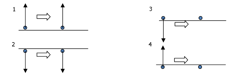
The problem is that, if the node is placed on the shell element,
it cannot be said beforehand on which side the node will be seen. As a solution
to this situation, the element group should get permeability: nodes can
penetrate the element from one side but not from the other side. The new
command
CHECK_ELGR_BLOCKING = <BOTH | POS | NEG>
can have the following values:
| BOTH | (Default) element group is not penetrable from any side. Like current behavior with the known problems. |
| POS | Element group is penetrable in negative normal direction and blocking in positive normal direction. |
| NEG | Element group is penetrable in positive normal direction and blocking in negative normal direction. |
If a node sits slightly above the barrier elements and gets moved away from it without hitting
the barrier, it might be desired to block the node movement. The TOLERANCE
parameter can be used for virtually displacing nodes in the opposite moving direction. Nodes
that are located close enough to the barrier are lying virtually on the correct side to get
blocked. TOLERANCE is given as an absolute (positive) value and its default
is roughly 10% of the mean edge length. It gets only applied with
CHECK_ELGR_BLOCKING equal to POS and
NEG, but not with BOTH.
Example:
DVCON_SHAPE
  ID_NAME             = DVC_PENETRATION_CHECK
  ND_GROUP            = some_node_group
  CHECK_ELGR          = barrier_elements
  CHECK_ELGR_BLOCKING = POS
END_
-
CHECK_ELGRrestrictions can be performed for surface nodes as well as for inner nodes. To limit the exterior form of a component, it only makes sense to restrict surface nodes. However, the node displacements in theMESH_SMOOTHarea should be limited.
 |
-
Up to six
CHECK_ELGRparameters can be defined in everyDVCON_SHAPEcommand. They are executed in the order of their declaration within theDVCON_SHAPEcommand. For each group a newPENETRATION_CHECKentry must be created. - To simplify the definition of the contact check, it is useful to divide the limiting surfaces by assigning various element property numbers (or materials). This greatly simplifies the selection and assembly of groups in the optimization preprocessor (when using manual selection).
Important:
|
- In sensitivity-based optimization mode, the node
restrictions
CHECK_SOLIDandCHECK_ELGRare applied as box constraints on the design variables. These commands can be used as an alternative or in addition toCHECK_SHRINKandCHECK_GROWto restrict the design nodes.