About Prevention of Undercuts in the Model | ||||||
|
| |||||
In many cases where bending and torsion loads are applied, the topology optimization leads to models with hollow areas or models with undercuts. A direct manufacturing of these results can be very challenging or straight up infeasible. To convert the result of a nonrestricted topology optimization into a manufacturable design, a lot of manual post-processing changes are necessary. These changes might modify the mechanical properties dramatically. The solution for this problem is to include the manufacturing constraints directly in the topology optimization.
The following figure shows the difference between the two optimization results: without manufacturing constraints (left) and with casting constraint to prevent undercuts (right):
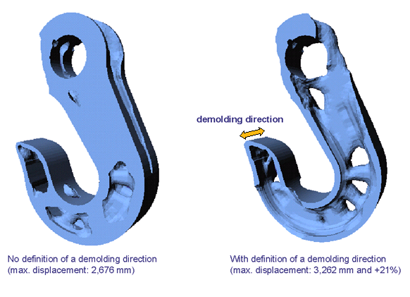
The formation of cavities and undercuts during the topology optimization can be prevented by using the casting constraint in the design variable constraint definition. This significantly simplifies the transfer of topology optimization results into manufacturable components. Solutions are limited as in the case of all other kinds of restrictions.
| Tip: Usually, it is better to carry out the optimization without manufacturing restrictions first, and then to perform a second optimization with manufacturing restrictions. |
Command Definition
A manufacturing constraint for the prevention of undercuts (CHECK_TYPE = CAST) is usually defined by the following parameters:
-
ELEMENT_GROUP: The group which the restriction should be applied on. -
MID_PLANE: The midplane generally defines the parting plane of the molds. It is also used indirectly to differ between a single extrusion, a split extrusion, or stamping. -
PULL_DIR: The direction in which the restriction should be enforced. In general, this is the direction in which the molds are pulled off the part to free it. In this section about the prevention of undercuts, the terms ‘casting direction,’ ‘demolding direction,’ and ‘pull direction’ are used as synonyms depending on the context.Note: If a cylindrical coordinate system is used, the pull direction must be the polar axis (1,0,0). The restriction then prevents undercuts in radial directions.
Refer to the DVCON_TOPO documentation for a full description of all available command items.
Group Definitions
For a definition of a demold restriction, two element groups are needed:
- The first group is the "casting group," defined by the
ELEMENT_GROUPentry. It contains all elements where the restriction should be active. It must be a subset of the design element group. - The second group is the "check group," defined by the
CHECK_GROUPentry. When it is checked if an element is allowed to be removed, this test is performed with respect to the elements in the check group. The check group should include all elements of the casting group.Note: The elements outside of the casting group are treated as a barrier if they are included in the check group. This means that the elements in the optimization group cannot be removed "through" these other elements. The same applies to frozen regions. If an element in the check group is frozen, the optimization result may contain a lot of unnecessary material to prevent undercuts behind this element. If this is not the desired result, the frozen elements simply must be removed from the check group.
Midplane Types
There are four different variants to check for undercuts and cavities that can be selected
by the parameter MID_PLANE:
-
Using a pull direction without the middle plane (
MID_PLANE = NONE). Only the pull direction is defined. A fictitious middle plane lies outside of the component, so pulling takes place in only one direction. -
Using a pull direction with a fixed middle plane (
MID_PLANE = POINT). A middle plane is defined by a point and the pull direction (vector perpendicular to the middle plane). It is checked that the component is demoldable in both directions away from the middle plane. -
Using a pull direction and the automatically defined middle plane
(
MID_PLANE = AUTO). Tosca Structure determines the optimal position of the middle plane for each area. -
Using the normal directions of the original model surface (
MID_PLANE = SURFACE). For each element, the pull direction is defined by the surface-normal at the closest surface point (only the surface of the elements from the casting group is considered and the direction is not updated during the optimization). The midplane typeSURFACEis useful for models where the pull direction is not already known, as shown in the following figure: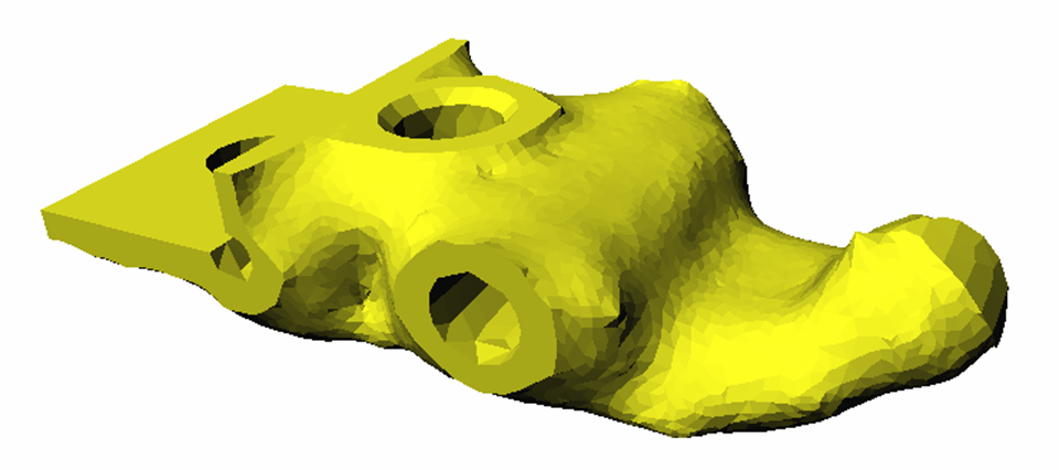
A pull direction vector (PULL_DIR) must be defined for the types 1-3. The
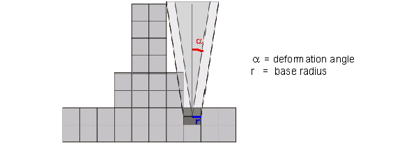
deformation angle (ANGLE) defines the necessary angle needed for ejection.
Values between 0° and 20° are permitted. Checking the pull direction is made with the help
of a pull cone starting at the centroid of the respective element. That the pull direction
is maintained is checked using the pull cone with a certain base radius. This radius is
based on the average element size and is usually determined from the model.
Example: Deformation Angle
The following figure shows a pull cone with a deformation angle centered at the element enlarged by base radius r.
The specification of this RADIUS is optional and is only
necessary for models that have elements of very different sizes. If a
value is specified, it should be larger than approximately 50% of the
average element edge length.
The following figure shows an engine mount with and without manufacturing restrictions:

Members of the specified element group are only modified if they can be removed from the model in the pull direction, so that internal cavities and recesses cannot be formed.
Important:
|