About the Definition of Overhang Restrictions | ||
| ||
Overhang Constraint Definition
A printing restriction is activated by setting the check type of the design variable constraint to OVERHANG.
The restriction is defined by the following parameters:
ELEMENT_GROUP: The group of elements for which the constraint is active. If left out the constraint will be active for all design elements.CHECK_GROUP: The group of elements that will be used in the internal check if elements are properly supported and do not violate the overhang angle criteria. All elements will be used if this parameter is not used.PRINT_DIR: The direction in which the model is supposed to be printed. This is the only parameter that should always be set when using the overhang constraint.PRINT_CS: The coordinate system the printing direction is defined in. If omitted it is assumed that the direction is given in the default coordinates.ANGLE: The maximum allowed angle of overhanging structures. Overhangs that exceed this angle will be prevented. The default value is 45 degrees.RADIUS: With this parameter, you can define the size of the cones that are used in the internal check for the overhang criteria. Usually the default value of 1.5 times the average element length does not need to be changed.BASE_PLANE: This parameter allows the definition of the printing bed. Only the elements that are situated above the printing bed need support.SUPPORT_FROZEN: This switch enables the support of functional regions. By default, functional regions are not considered by the overhang constraint.
Overhang Check
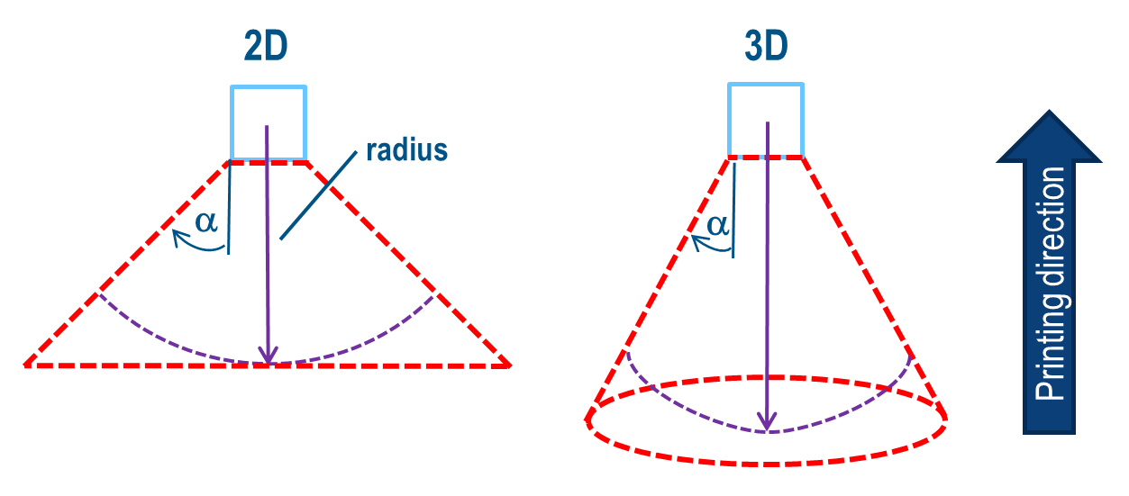
To identify if a model contains critical overhangs, an internal check using element cones is used. If all elements inside a cone are being removed due to the topology optimization process, the cone top is not properly supported anymore in terms of the overhang criteria. The top element will then be removed to ensure that the constraint is fulfilled. A cone definition is described in the following figure:
 |
Example: 2D Beam
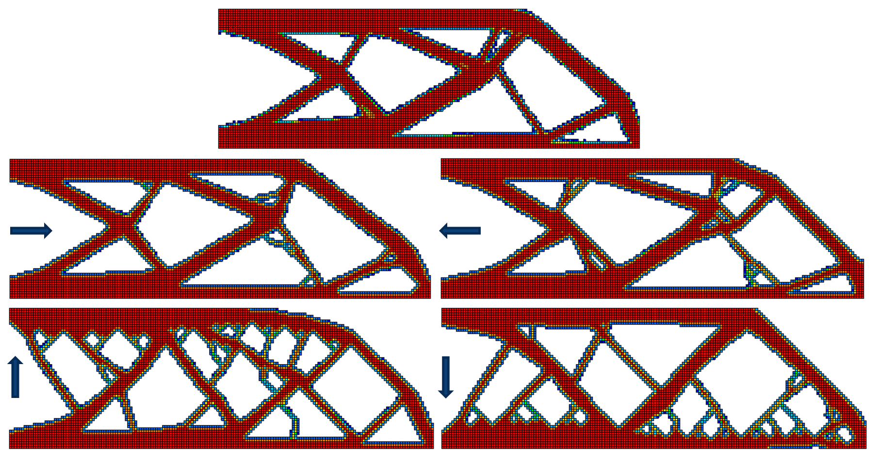
How the overhang constraint influences the design of the result can be seen in the example below. The model in this case is a simple 2D bending beam that is fixed on the left with a force applied at the lower-right corner. The figure shows the result for four different printing directions—each time limiting the overhang angle to a maximum of 45°.
The parameter file command that is used in this example looks like the following:
DVCON_TOPO
 ID_NAME    = MY_DVCON_TOPO
 EL_GROUP   = ALL_ELEMENTS
 CHECK_TYPE = OVERHANG
 PRINT_DIR  = 0.0, 1.0, 0.0
 ANGLE      = 45
END_
Example: Define the Printing Bed
Some models contain overhanging structures. This means that the outer surface violate the angle
criteria and would require support structures during printing. By default, the overhang
constraint will try to remove all overhanging features so results do not need additional support
structures. Depending on the geometry, this will lead to unreasonable results where, for
example, the force is disconnected from the fixture. To give the user control how these global
overhangs should be treated by the constraint the BASE_PLANE option was
introduced.
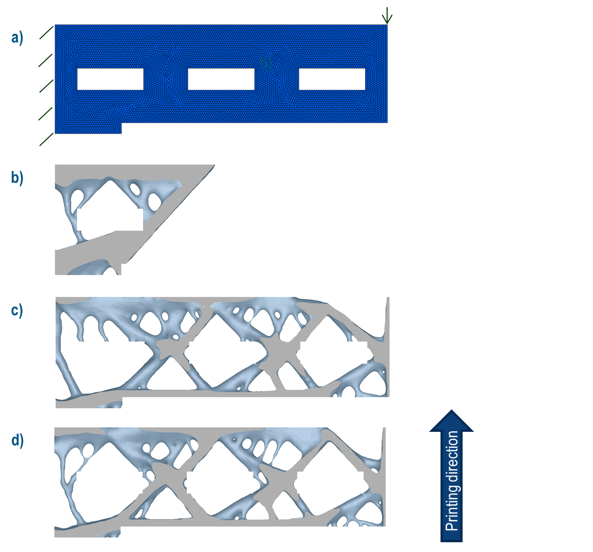
In the above image, the original model (a) contains multiple overhangs, one at the bottom and one
above each of the holes. For a 45° angle, the default option of the constraint will always lead
to a disconnection of the right-hand side since it is impossible to design without overhanging
structures (b, BASE_PLANE=AUTO). However, if boundary elements should always be
printable (c, BASE_PLANE=NONE), there are undesired overhangs remaining in the
result above the holes. To obtain a result where the overhang at the bottom is ignored because
it is mandatory but the regions above the holes are free of overhangs, the base plane (or
printing bed) must be set to a user-defined point in space (d,
BASE_PLANE=POINT,X,Y;Z). This point should be located above the required overhangs
and under overhangs that should be removed.
Example: Overhanging Functional Regions
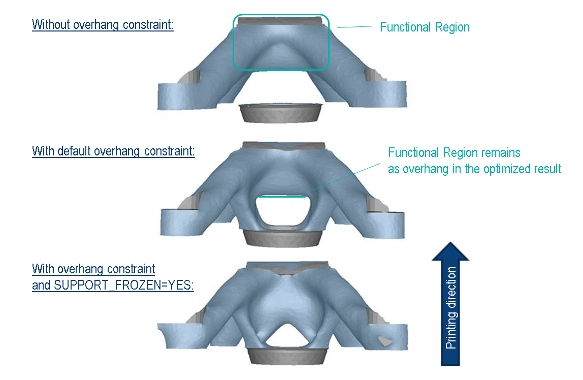
By default, the overhang constraint will not consider the functional/frozen regions that are present
in the model. This can lead to optimization results where the functional regions remain as
overhanging structures although an overhang constraint was used. With the
SUPPORT_FROZEN option, the constraint tries to alter the design in such a way
that frozen regions are not overhanging. However, it cannot be guaranteed that the functional
regions will be fully supported by underlying material. It is strongly advised to not use this
option on the first optimization run and only if the default result does not satisfy the
requirements.
The parameter file command that is used in this example looks like the following:
DVCON_TOPO
 ID_NAME        = MY_DVCON_TOPO
 EL_GROUP       = ALL_ELEMENTS
 CHECK_TYPE     = OVERHANG
 PRINT_DIR      = 0.0, 1.0, 0.0
 ANGLE          = 45
 SUPPORT_FROZEN = YES
END_
Important:
|