Defining a Milling Restriction | ||
| ||
Milling Restriction Definition
A milling restriction is activated by setting the check type of the design variable constraint to MILLING.
The restriction is defined by the following parameters:
ELEMENT_GROUP: The group of elements for which the constraint is active. Defining an element group is mandatory.CHECK_GROUP: The group of elements that will be used in the internal check if elements are properly supported and do not violate the milling restriction. All elements will be used if this parameter is not used.MILLING_DIR: The direction in which the model is supposed to be milled. This is the only parameter that should always be set when using the milling restriction.MILLING_CS: The coordinate system the milling direction is defined in. If omitted it is assumed that the direction is given in the default coordinates.
The parameter file command might look like the following:
DVCON_TOPO
  ID_NAME     = MY_DVCON_TOPO
  EL_GROUP    = ALL_ELEMENTS
  CHECK_TYPE  = MILLING
  MILLING_DIR = 1.0, 0.0, 0.0
  MILLING_DIR = 0.0, 1.0, 0.0
  MILLING_DIR = 0.0, 0.0, 1.0
END_
Milling Check
To identify if a model contains critical millable regions, an internal check is used. The
CHECK_GROUP will define all elements that should be taken into account
for checking how millable the part is. This check is identical to the one used in DVCON_TOPO
CAST. In each milling direction, a 2D contour will be forced through the
design area defined by ELEMENT_GROUP.
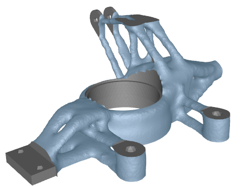
Example: Milling Functional Regions
The milling restriction will consider the functional/frozen regions that are present in the model if they are contained in the CHECK_GROUP.
This means that the contours of the frozen regions are not penetrated by the milling tool.
The parameter file command that is used in this example looks like the following:
DVCON_TOPO
  ID_NAME     = MY_DVCON_TOPO
  EL_GROUP    = ALL_ELEMENTS
  CHECK_GROUP = ALL_ELEMENTS
  CHECK_TYPE  = MILLING
  MILLING_DIR = 1.0, 0.0, 0.0
  MILLING_DIR = 0.0, 1.0, 0.0
  MILLING_DIR = 0.0, 0.0, 1.0
  MILLING_CS  = CS_0
END_
Important:
|