Constraints | ||||||||
|
| |||||||
Overview
The following table gives an overview of all supported design responses as a constraint in topology optimization:| Static analysis | Description |
CENTER_GRAVITY_X CENTER_GRAVITY_Y CENTER_GRAVITY_Z |
Center of gravity design responses |
DENSITY_MEASURE |
Density measure design response |
DISP_ABS DISP_X DISP_Y DISP_Z DISP_X_ABS DISP_Y_ABS DISP_Z_ABS |
Displacement design responses |
ENERGY_STIFF_MEASURE |
Energy Stiffness Measure design response |
INERTIA_XX INERTIA_XY INERTIA_XZ INERTIA_YY INERTIA_YZ INERTIA_ZZ |
Moment of inertia design responses |
INTERNAL_FORCE_ABS INTERNAL_FORCE_X INTERNAL_FORCE_Y INTERNAL_FORCE_Z INTERNAL_FORCE_X_ABS INTERNAL_FORCE_Y_ABS INTERNAL_FORCE_Z_ABS |
Internal force design responses |
INTERNAL_MOMENT_ABS INTERNAL_MOMENT_X INTERNAL_MOMENT_Y INTERNAL_MOMENT_Z INTERNAL_MOMENT_X_ABS INTERNAL_MOMENT_Y_ABS INTERNAL_MOMENT_Z_ABS |
Internal moment design responses |
REACTION_FORCE_ABS REACTION_FORCE_X REACTION_FORCE_Y REACTION_FORCE_Z REACTION_FORCE_X_ABS REACTION_FORCE_Y_ABS REACTION_FORCE_Z_ABS |
Reaction force design responses |
REACTION_MOMENT_ABS REACTION_MOMENT_X REACTION_MOMENT_Y REACTION_MOMENT_Z REACTION_MOMENT_X_ABS REACTION_MOMENT_Y_ABS REACTION_MOMENT_Z_ABS |
Reaction moment design responses |
ROT_ABS ROT_X ROT_Y ROT_Z ROT_X_ABS ROT_Y_ABS ROT_Z_ABS |
Rotation design responses |
SIG_1 |
Maximum principal stress. |
SIG_3 |
Minimum principal stress. |
SIG_SENS_MISES |
Von Mises Stress design responses
|
SIG_SIGNED_MISES |
Signed von Mises stress failure criteria. |
SIG_GLINKA_EEQ SIG_GLINKA_PEEQ SIG_GLINKA_SEQ SIG_NEUBER_EEQ SIG_NEUBER_PEEQ SIG_NEUBER_SEQ |
Glinka and Neuber formulations for equivalent strain (_EEQ), stress (_SEQ) and plastic strain (_PEEQ) using the plastic correction factor, respectively**. |
STRAIN_ENERGY |
Strain energy design response* |
WEIGHT |
Weight design response |
VOLUME |
Volume design response |
| Modal analysis | Description |
DYN_FREQ |
Dynamic frequency design response |
| Thermal analysis | Description |
ENERGY_THERMAL_MEASURE |
Energy thermal measure design response |
INTERNAL_HFLUX |
Internal heat flux design response |
REACTION_HFLUX |
Reaction heat flux design response |
TEMPERATURE |
Temperature design response |
Important:
|
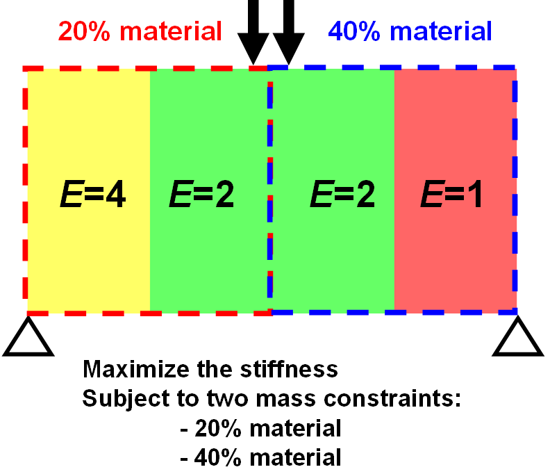
Multiple Material Constraints and Constitutive Laws
Multiple material constraints and constitutive laws are allowed in the design domain. That is, different sub domains of the total design domain can be subject to different material volume constraints. In addition, different sub domains are allowed to have different constitutive material laws.
Important:
The DRESP WEIGHT_TOPO_FILL is not allowed when the
design area contains different materials. |
The following figure shows the design domain consisting of three different materials. Two volume constraints are applied in the design domain. The elements on the left side have the volume constraint of 20%, and the elements on the right side have the volume constraint of 40%.
 |
The design element group contains all elements:
DV_TOPO
 ID_NAME    = DESIGN_VARIABLES
 EL_GROUP   = ALL_ELEMENTS
END_
Then, using the groups ELEM_LEFT (left part of the
model) and ELEM_RIGHT (right part of the model), two
separate design responses are defined:
DRESP
 ID_NAME    = DRESP_VOL_TOPO_LEFT
 DEF_TYPE   = SYSTEM
 TYPE       = VOLUME
 EL_GROUP   = ELEM_LEFT
 GROUP_OPER = SUM
END_

DRESP
 ID_NAME    = DRESP_VOL_TOPO_RIGHT
 DEF_TYPE   = SYSTEM
 TYPE       = VOLUME
 EL_GROUP   = ELEM_RIGHT
 GROUP_OPER = SUM
 END_
Afterward, these design responses are applied in the relative volume constraints:
CONSTRAINT
 ID_NAME    = VOLUME_CONSTRAINT_LEFT
 DRESP      = DRESP_VOL_TOPO_LEFT
 MAGNITUDE  = REL
 LE_VALUE   = 0.2
END_

CONSTRAINT
 ID_NAME    = VOLUME_CONSTRAINT_RIGHT
 DRESP      = DRESP_VOL_TOPO_RIGHT
 MAGNITUDE  = REL
 LE_VALUE   = 0.4
 END_
It is not allowed for the element groups with different volume constraints to have common elements. In other words, each element can be used in no more than one volume constraint. The compliance is minimized in the objective to maximize the stiffness:
DRESP
 ID_NAME    = DRESP_SUM_ENERGY
 DEF_TYPE   = SYSTEM
 TYPE       = STRAIN_ENERGY
 EL_GROUP   = ALL_ELEMENTS
 GROUP_OPER = SUM
END_

OBJ_FUNC
 ID_NAME    = MAXIMIZE_STIFFNESS
 DRESP      = DRESP_SUM_ENERGY
 TARGET     = MIN
END_
Finally, the commands defined above are referenced in OPTIMIZE command:
OPTIMIZE
 ID_NAME    = TOPOLOGY_OPTIMIZATION
 DV         = DESIGN_VARIABLES
 OBJ_FUNC   = MAXIMIZE_STIFFNESS
 CONSTRAINT = VOLUME_CONSTRAINT_LEFT
 CONSTRAINT = VOLUME_CONSTRAINT_RIGHT
END_
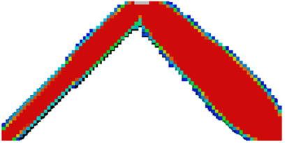
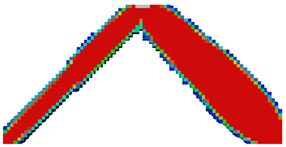
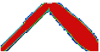
The following figures show the results of the optimization.
Abaqus |
ANSYS® |
Nastran |
 |
 |
 |