Defining the Design Area and Frozen Area
-
Define the Design Area as follows:
DV_TOPO
  ID_NAME  = DESIGN_VARIABLES
  EL_GROUP = ALL_ELEMENTS
END_
-
To define the Frozen Area, do the following:
-
Define a Group Definition (GROUP_DEF) with the elements that are supposed to be frozen:
GROUP_DEF
  ID_NAME = TOP_FROZEN
  TYPE    = ELEM
  FORMAT  = LIST
  LIST_BEGIN
  9801-10000
END_
-
Reference the Group Definition in a Design Variable Constraint (DVCON_TOPO):
DVCON_TOPO
  ID_NAME    = DVCON_FROZEN
  EL_GROUP   = TOP_FROZEN
  CHECK_TYPE = FROZEN
END_
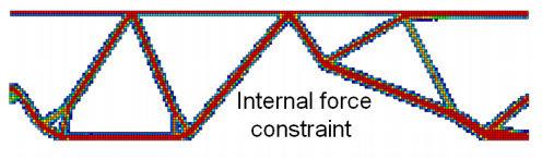
First Approach: Defining a Constraint by Internal Forces
In the first approach, a constraint is defined for the sum of internal forces through a
cut in the y-direction of the beam structure.
-
Create a Group Definition (GROUP_DEF) for a node group as follows:
GROUP_DEF
  ID_NAME = ND_INTERNAL_GROUP
  TYPE    = NODE
  FORMAT  = LIST
  LIST_BEGIN
  149,476,751,1078,1353,1680,1955,2282,2557,2884,3159,3486,
  3761,4088,4363,4690,4965,5292,5567,5894,6169,6496,6771,
  7098,7373,7700,7975,8302,8577,8904,9179,9506,9781,10108,
  10383,10710,10985,11312,11587,11914,12189,12516,12791,
  13118,13393,13720,13995,14322,14597,14924,15199,
  15526-20551:201,
  20826,21153,21428,21755,22030,22357,22632,22959,23234,
  23561,23836,24163,24438,24765,25040,25367,25642,25969,
  26244,26571,26846,27173,27448,27775,28050,28377,28652,
  28979,29254,29581,29856,30183,30458,30785,31060,31387,
  31662,31989,32264,32591,32866,33193,33468,33795,34070,
  34397,34672,34999,35274,35601,35876,36604,36879,37206,
  37481,37808,38083,38410,38685,39012,39287,39614,39889,
  40216,40491,40818,41093,41420,41695,42022,42297,42624,
  42899,43226,43501,43828,44103,44430,44705,45032,45307,
  45634,45909,46236,46511,46838,47113,47440,47715,48042,
  48317,48644,48919,49246,49521,49848,50123,50450,50725,
  51052,51327
END_
This group sums up the internal forces in the y-direction.
-
Create a Group Definition (GROUP_DEF) for an element group as follows:
GROUP_DEF
  ID_NAME = EL_INTERNAL_GROUP
  TYPE    = ELEM
  FORMAT  = LIST
  LIST_BEGIN
  75-9875:200
END_
-
Create a Design Response (DRESP) as follows:
DRESP
  ID_NAME    = DRESP_INT_Y_SUM
  TYPE       = INTERNAL_FORCE_Y
  DEF_TYPE   = SYSTEM
  GROUP_OPER = SUM
  ND_GROUP   = ND_INTERNAL_GROUP
  EL_GROUP   = EL_INTERNAL_GROUP
END_
In this approach the internal forces is summed up in the y-direction for the
previously defined node and element group yielding. Note:
GROUP_OPER=SUM is extremely important because default is
GROUP_OPER=MAX. See also the User Manual.
In this approach, the internal forces is summed up in the y-direction for the
previously defined node and element group yielding. Note:
GROUP_OPER=SUM is extremely important because the default is
-
Create a constraint (CONSTRAINT) as follows:
CONSTRAINT
  ID_NAME   = CON_INT_Y_SUM
  DRESP     = DRESP_INT_Y_SUM
  MAGNITUDE = ABS
  GE_VALUE  = 0.0015
END_
The constraint enforces that more than half of the applied force P (P/2=0.00015) should be
transferred to the boundaries on the right side.
-
To define the Objective Function, do the following:
-
Define a Design Response (DRESP) as follows:
DRESP
  ID_NAME    = DRESP_SUM_ENERGY
  DEF_TYPE   = SYSTEM
  TYPE       = STRAIN_ENERGY
  EL_GROUP   = ALL_ELEMENTS
  GROUP_OPER = SUM
END
-
Reference the Design Response in the Objective Function (OBJ_FUNC):
OBJ_FUNC
  ID_NAME = MAXIMIZE_STIFFNESS
  DRESP   = DRESP_SUM_ENERGY
  TARGET  = MIN
END_
In this way, the sum of strain energy is minimized for
obtaining a stiff structure.
-
To constrain the volume to 15 % compared to the existing model, do the following:
-
Define a Design Response (DRESP) as follows:
DRESP
  ID_NAME    = DRESP_VOL_TOPO
  DEF_TYPE   = SYSTEM
  TYPE       = VOL_TOPO_FILL
  EL_GROUP   = ALL_ELEMENTS
  GROUP_OPER = SUM
END
-
Reference the Design Response in a constraint (CONSTRAINT):
CONSTRAINT
  ID_NAME   = VOLUME_CONSTRAINT
  DRESP     = DRESP_VOL_TOPO
  MAGNITUDE = REL
  LE_VALUE  = 0.15
END_
-
Reference the Design Variables, Objective Function and Constraints in the OPTIMIZE command:
OPTIMIZE
  ID_NAME    = TOPOLOGY_OPTIMIZATION
  DV         = DESIGN_VARIABLES
  OBJ_FUNC   = MAXIMIZE_STIFFNESS
  DVCON      = DVCON_FROZEN
  CONSTRAINT = VOLUME_CONSTRAINT
  CONSTRAINT = CON_INT_Y_SUM
END_
-
To stabilize the optimization, define a stricter update of design variables as follows:
OPT_PARAM
  ID_NAME        = SPECIAL
  OPTIMIZE       = TOPOLOGY_OPTIMIZATION
  DENSITY_UPDATE = CONSERVATIVE
  DENSITY_MOVE   = 0.1
END_
The result looks as follows:
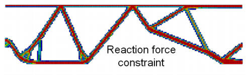
Second Approach: Defining a Constraint by Reaction Forces
In the second approach, a constraint is defined for the sum of reaction forces in the
y-direction for all the nodes on the left side of the beam structure.
-
Create a Group Definition (GROUP_DEF) for a node group as follows:
GROUP_DEF
  ID_NAME = ND_INTERNAL_GROUP
  TYPE    = NODE
  FORMAT  = LIST
  LIST_BEGIN
  149,476,751,1078,1353,1680,1955,2282,2557,2884,3159,3486,
  3761,4088,4363,4690,4965,5292,5567,5894,6169,6496,6771,
  7098,7373,7700,7975,8302,8577,8904,9179,9506,9781,10108,
  10383,10710,10985,11312,11587,11914,12189,12516,12791,
  13118,13393,13720,13995,14322,14597,14924,15199,
  15526-20551:201,
  20826,21153,21428,21755,22030,22357,22632,22959,23234,
  23561,23836,24163,24438,24765,25040,25367,25642,25969,
  26244,26571,26846,27173,27448,27775,28050,28377,28652,
  28979,29254,29581,29856,30183,30458,30785,31060,31387,
  31662,31989,32264,32591,32866,33193,33468,33795,34070,
  34397,34672,34999,35274,35601,35876,36604,36879,37206,
  37481,37808,38083,38410,38685,39012,39287,39614,39889,
  40216,40491,40818,41093,41420,41695,42022,42297,42624,
  42899,43226,43501,43828,44103,44430,44705,45032,45307,
  45634,45909,46236,46511,46838,47113,47440,47715,48042,
  48317,48644,48919,49246,49521,49848,50123,50450,50725,
  51052,51327
END_
This group sums up the reaction forces in the y-direction.
-
Create a Design Response (DRESP) as follows:
DRESP
  ID_NAME    = DRESP_REAC_Y_SUM
  TYPE       = REACTION_FORCE_Y
  DEF_TYPE   = SYSTEM
  GROUP_OPER = SUM
  ND_GROUP   = ND_REACTION_GROUP
END_
Note:
GROUP_OPER=SUM is extremely important because the default is
GROUP_OPER=MAX. See also the User Manual.
-
Create a constraint (CONSTRAINT) as follows:
CONSTRAINT
  ID_NAME   = CON_REAC_Y_SUM
  DRESP     = DRESP_REAC_Y_SUM
  MAGNITUDE = ABS
  LE_VALUE  = 0.0015
END_
The constraint enforces that more than half of the applied force P (P/2=0.00015)
should be transferred to the boundaries on the right side.
-
To constrain the volume to 15 % compared to the existing model, do the following:
-
Define a Design Response (DRESP) as follows:
DRESP
  ID_NAME    = DRESP_VOL_TOPO
  DEF_TYPE   = SYSTEM
  TYPE       = VOL_TOPO_FILL
  EL_GROUP   = ALL_ELEMENTS
  GROUP_OPER = SUM
END_
-
Reference the Design Response in a constraint(CONSTRAINT):
CONSTRAINT
  ID_NAME   = VOLUME_CONSTRAINT
  DRESP     = DRESP_VOL_TOPO
  MAGNITUDE = REL
  LE_VALUE  = 0.15
END_
-
Reference the Design Variables, Objective Function and Constraints in the OPTIMIZE command:
OPTIMIZE
  ID_NAME    = TOPOLOGY_OPTIMIZATION
  DV         = DESIGN_VARIABLES
  OBJ_FUNC   = MAXIMIZE_STIFFNESS
  DVCON      = DVCON_FROZEN
  CONSTRAINT = VOLUME_CONSTRAINT
  CONSTRAINT = CON_REAC_Y_SUM
END_
The result looks as follows:
|