CS_DEF | ||||||
|
| |||||
ID_NAME |
= |
Name of the coordinate system |
CS_TYPE |
= RECTANGULAR = CYLINDRICAL = SPHERICAL |
Type of new coordinate system |
DEF_TYPE |
= LOCAL |
|
= NODE |
Definition using three nodes |
|
= VECTOR |
Definition using an origin and three vectors |
Items for DEF_TYPE = LOCAL
CS_REF |
= |
Existing reference coordinate system |
ORIGIN_123 |
= |
Coordinate values of the origin |
ROTATION_321 |
= |
Rotations that should be superimposed on the reference coordinate system |
Items for DEF_TYPE = NODE
CS_AXIS |
Specifies the axis and the plane defined by the three nodes. |
|
= X_XY |
X-axis and the X-Y plane are defined by the three nodes. |
|
= X_XZ |
X-axis and X-Z plane are defined by the nodes. |
|
= Z_XZ |
Z-axis and X-Z plane are defined by the nodes. |
|
NODE_ORIGIN |
= |
ID of node which defines the origin |
NODE_AXIS |
= |
ID of the node on the axis |
NODE_PLANE |
= |
ID of the node on the given plane and the second axis |
Items for DEF_TYPE = VECTOR
ORIGIN |
= |
Coordinate values of the origin |
VECTOR_X |
= |
Direction of the first reference vector. |
VECTOR_Y |
= |
Direction of the second reference vector. |
VECTOR_Z |
= |
Direction of the third reference vector. |
Remark
The rotation matrix given by
VECTOR_X,VECTOR_Y,VECTOR_Zmust have a determinant of 1:- The rotation angles in the command
ROTATION_321are in degrees. The single rotations are carried out in series around the axis of the local Cartesian coordinate. The following figure shows the rotations forROTATION_321 = 180.0, 0.0, 90.0: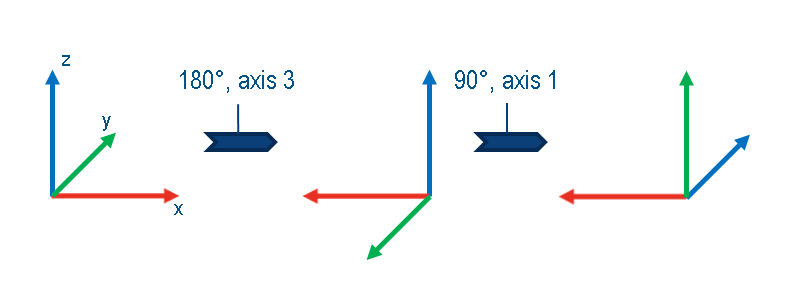
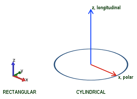
- The longitudinal axis of a cylindrical coordinate system is defined by the z-axis of the referenced rectangular coordinate system.
Respectively, the polar axis equals the x-axis, as shown in the following image:
Examples
The following command defines a cylindrical coordinate system with origin (10,20,0) with respect to the global Cartesian coordinate system CS_0.
The polar axis and longitudinal axis are obtained by rotating the x-axis and z-axis of CS_0 respectively by 45° around the z-axis and by 15° around the y-axis of CS_0.
CS_DEF
  ID_NAME      = my_cs_01
  CS_TYPE      = CYLINDRICAL
  DEF_TYPE     = LOCAL
  CS_REF       = cs_0
  ORIGIN_123   = 10.0, 20.0, 30.0
  ROTATION_321 = 45.0, 15.0, 0.0
END_
The following command defines a rectangular (Cartesian) coordinate system with origin through the node with ID number 10. The x-axis is defined by the nodes 10 and 100. Node 101 defines a point in the x-y plane.
CS_DEF
  ID_NAME     = my_cs_02
  CS_TYPE     = RECTANGULAR
  DEF_TYPE    = NODE
  CS_AXIS     = X_XY
  NODE_ORIGIN = 10
  NODE_AXIS   = 100
  NODE_PLANE  = 101
END_
The following command defines a rectangular (Cartesian) coordinate system with origin (10,10,10). The x-axis is defined by the vector (-1,0,0), y-axis with the vector (0,-1,0) and the z-axis with (0,0,-1).
CS_DEF
  ID_NAME  = my_cs
  CS_TYPE  = RECTANGULAR
  DEF_TYPE = VECTOR
  ORIGIN   = 10,10,10
  VECTOR_X = -1,0,0
  VECTOR_Y = 0,-1,0
  VECTOR_Z = 0,0,-1
END_