Elements tested
GAPUNI
GAPCYL
GAPSPHER
ProductsAbaqus/Standard Elements testedGAPUNI GAPCYL GAPSPHER Problem descriptionSimple beam models are used to verify unidirectional, cylindrical, and spherical gap elements. GAPUNI with positive gap clearance
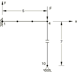
GAP data: Initial clearance = 0.5. X, Y, Z direction cosine of the closure direction = (0., −1., 0.). Boundary conditions: node 1 is clamped, and node 10 is fixed in the x- and y-directions. Loading case 1: = −50 at node 4; Loading case 2: = −100 at node 4. GAPCYL with positive gap clearance
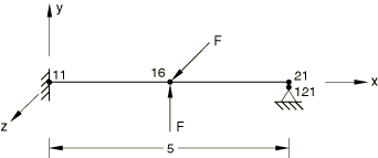
GAP data: Initial clearance = 0.0208 (positive gap clearance). X, Y, Z direction cosine of the cylinder axis = (1., 0., 0.). Boundary conditions: node 11 is clamped, node 121 is fixed in the x-, y- and z-directions. Loading: Step 1: = 2.0 × 10⁴ at node 16; Step 2: = 3.0 × 10⁴ at node 16. GAPCYL with negative gap clearance
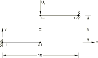
GAP data: Initial clearance = −1.0 (negative gap clearance). X, Y, Z direction cosine of the cylinder axis = (1., 0., 0.). Boundary conditions: nodes 11 and 12 are clamped, = −5.0 at node 22. GAPSPHER with positive gap clearance
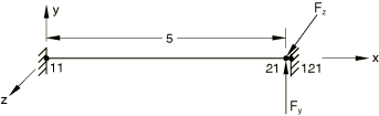
GAP data: Initial clearance = 0.2080. Boundary conditions: nodes 11 and 121 are clamped. Loading case 1: = 2.0 × 10⁴ and = 3.0 × 10⁴ at node 21; Loading case 2: = 4.0 × 10⁴ and = 6.0 × 10⁴ at node 21. The NLGEOM parameter is used. Results and discussionThe contact constraints are satisfied properly. Input files
| |||||||