Typical Applications
Thermal fluid pipe elements are used to simulate:
- the flow of a liquid through a pipe or network of pipes to determine pressure drops and flow rates, and
- the temperature field in the flowing fluid and the pipe walls.
Products Abaqus/Standard Typical ApplicationsThermal fluid pipe elements are used to simulate:
Choosing an Appropriate ElementSeveral thermal fluid pipe elements are available. They can be broadly classified as regular thermal fluid pipe elements or annular thermal fluid pipe elements. Element types FP2D2T and FP3D2T belong to the class of regular thermal fluid pipe elements. Element types FP2D2AT and FP3D2AT belong to the class of annular thermal fluid pipe elements. For two-dimensional analyses, use element type FP2D2T or FP2D2AT. For three-dimensional analyses, use element type FP3D2T or FP3D2AT. In the following paragraphs, the differences between the regular and the annular element families are discussed. Figure 1 shows a regular thermal fluid pipe element. It consists of a total of six nodes, three at each end of the element. Although each end has three distinct nodes, they actually share the same geometric location. The first node at each end (depicted blue in Figure 1) is used to model the fluid flow and has both fluid pressure and temperature degrees of freedom. These nodes are referred to as the "flow nodes." The second and third nodes at each end (depicted red in Figure 1) define the temperature variation through the wall of the pipe and have only the temperature degree of freedom. These nodes are referred to as the "wall nodes." The element connectivity for the regular thermal fluid pipe elements is shown in Figure 2. 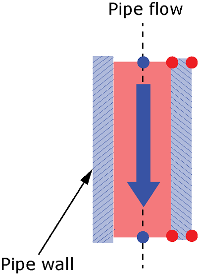 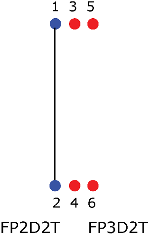 Figure 3 shows an annular pipe, which consists of a center region that is the same as a regular pipe (and should be modeled with a regular thermal fluid pipe element) and an annular region that surrounds the center region. The annular region, which must be modeled using an annular thermal fluid pipe element, has a total of eight nodes, four at each end of the pipe sharing the same geometric location. The nodes at the middle of the annulus (depicted blue in Figure 3) have both fluid pressure and temperature degrees of freedom; they are referred to as the "flow nodes." The "wall nodes" (depicted red in Figure 3) have only temperature degrees of freedom and model the temperature variation in the inner and outer walls of the annulus. The element connectivity for the annular thermal fluid pipe element is shown in Figure 4. 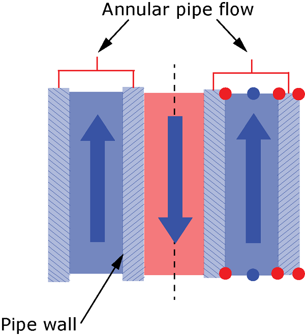 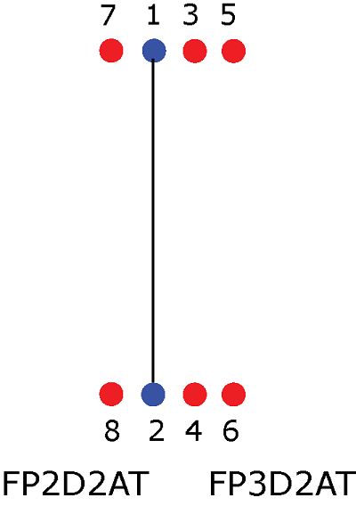 A typical application of the annular pipe element involves the modeling of return flow in a piping system. As shown in Figure 3, the fluid flow directions in the center and the annular regions might be opposite to each other. The incoming fluid at the center region and the outgoing fluid in the annular region can be at different temperatures. The temperature degree of freedom at the outermost wall nodes of the regular pipe region (nodes 5 and 6 in Figure 2) and that at the corresponding innermost wall nodes of the annular region (nodes 7 and 8 in Figure 4) must be tied to ensure continuity of the temperature field between the center and the annular regions. In addition, if return flow is modeled, the fluid pressure and temperature degrees of freedom of the bottom "flow node" of the regular thermal fluid pipe element (node 2 in Figure 2) must be tied to the corresponding degrees of freedom of the bottom "flow node" of the annular thermal fluid pipe element (node 2 in Figure 4). You can use an offset to create the pipe wall nodes of the regular thermal fluid pipe and annular thermal fluid pipe elements. You can render thermal pipe elements and annular thermal pipe elements using the Visualization module of Abaqus/CAE. For more information, see Controlling the display of thermal fluid pipe elements. Input File Usage Use the following option to define an offset used to create the pipe wall nodes: ELEMENT, OFFSET=number Assigning a Material Definition to a Set of Fluid Pipe ElementsYou must associate a material definition with each pipe element section property. The material that is defined for the thermal fluid pipe section refers to the fluid that is flowing through the pipe. You must define the following properties for the fluid to describe its flow behavior: fluid density and viscosity. For the viscosity definition, thermal fluid pipe elements support both Newtonian and non-Newtonian fluids. The following non-Newtonian fluid models are supported: power law, Bingham Plastic, and Herschel-Bulkley models (see Viscosity). For the thermal fluid pipe elements, you must also specify the following thermal properties:
Input File Usage Use the following options to specify the flow and thermal behaviors of the fluid: FLUID PIPE SECTION, MATERIAL=material name MATERIAL, NAME=material name VISCOSITY, DEFINITION=NEWTONIAN or POWER LAW or HERSCHEL-BULKLEY or BINGHAM PLASTIC DENSITY, PORE FLUID CONDUCTIVITY, PORE FLUID SPECIFIC HEAT, PORE FLUID In addition, use the following options to specify the thermal properties for the pipe wall: DENSITY CONDUCTIVITY SPECIFIC HEAT Using Thermal Fluid Pipe Elements in Symmetric ModelsYou can use thermal fluid pipe elements in models that use symmetry to reduce the model size. The thermal fluid pipe elements model circular geometry. You specify a symmetry value that is greater than 0 or less than or equal to 1. This value is interpreted as scaling of the circular pipe geometry in radians. A value of 1 corresponds to radians, and a value of 0.5 corresponds to radians. When you specify symmetry, you must scale the full model flow magnitude by the symmetry value. You do not need to apply any symmetric constraints or boundary conditions. Input File Usage FLUID PIPE SECTION, SYMMETRY=value Thermal Fluid Pipe EquationsThe governing equations for the fluid flow and pressure drop computation in pipes are described in Fluid Pipe Equations. The different choices of specifying the frictional loss characteristics for the flowing fluid in the thermal pipe are described in Specifying the Friction Loss Behavior. You can model additional fluid pressure losses in thermal fluid pipe elements as described in Additional Loss Terms in Fluid Pipe Elements. In the thermal fluid pipe elements, the fluid temperature evolution is given by the 1-D transient advection-diffusion equation: where:
Specifying the Wall Diameters for Thermal Fluid Pipe ElementsYou must define the geometry of the pipe wall as a circular cross-section by specifying the inner and outer wall radii. Input File Usage FLUID PIPE WALL Specifying the Type of Convection between the Fluid and the Pipe WallYou can define the type of convection to determine the temperature at the interface of the pipe wall and flowing fluid (nodes 3 and 4 for the regular pipe and nodes 3, 4, 7, and 8 for the annular pipe). Newton's law of cooling is used to determine this interface temperature. The convection type determines whether a constant temperature or a constant flux method is used in this computation. Input File Usage Use the following option to specify a constant temperature method: FLUID PIPE THERMAL, TYPE=TEMPERATURE Use the following option to specify a constant flux method: FLUID PIPE THERMAL, TYPE=FLUX Specifying Initial and Prescribed ConditionsYou can define an initial temperature or field distribution over the nodes of the thermal fluid pipe elements. Input File Usage Use one or both of the following options: INITIAL CONDITIONS, TYPE=TEMPERATURE INITIAL CONDITIONS, TYPE=FIELD Specifying Loads and Boundary ConditionsThermal fluid pipe elements allow for the specification of pressure boundary conditions and volumetric flow rates at the nodes. At a particular node, you can specify either a pressure or flow rate but not both. You can also specify a gravity load on the thermal fluid pipe element to determine the hydrostatic head at the nodes. You can specify the fluid temperature at the inlet or outlet and at the pipe wall. Input File Usage Use the following option to specify the pressure at the inlet or outlet: BOUNDARY node or node set, 8, 8, magnitude Use the following option to specify the flow rate at the inlet or outlet: CFLOW node or node set, , magnitude Use the following option to specify the temperature at the inlet, outlet, or pipe wall: BOUNDARY node or node set, 11, 11, magnitude Use the following option to specify a gravity load on the fluid pipe element: DLOAD element or element set, , GRAV, gravity constant, comp1, comp2, comp3 | |||||||||||||||