Viewing the Mappings | ||
| ||
-
From the Design Gateway, click the
ApproxLoopExploration component icon .
.
-
Select a parameter on the left side of the tab to see its mapping. The
FuseLngthparameter is selected in the following figure: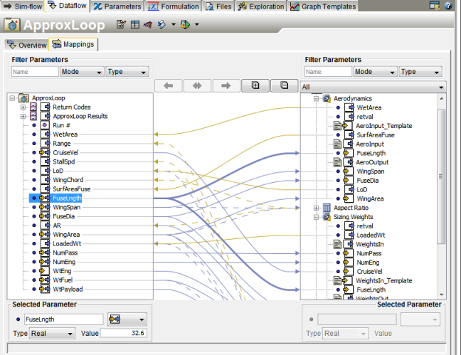
The preceding figure shows how the
ApproxLoopExploration component contains both in/out parameters. The yellow and blue arrows on the left side under the
 ApproxLoopExploration component indicate in/out parameters. Process components have in/out parameters because process components can send out the input parameter value and receive the output value. In addition, the figure shows the flexibility of mapping because theFuseLngthparameter in theApproxLoopExploration component maps to theFuseLngthparameter in theAerodynamicscomponent and to theSizing WeightsSimcode component. Yellow arrows show parameters that are input to theApproxLoopExploration component, and blue arrows show parameters that are output. You can click on a parameter to highlight its path between components.By default, Isight automatically maps parameters of the same name, value, and type between components (see Setting Parameter Preferences in the Database). However, if the name of a parameter changes from one component to another, you must manually define the mapping. (For example, if you are using a script from a third-party that has its own set of input and output parameters, you must map your parameters to the parameters that are expected by the script.)